
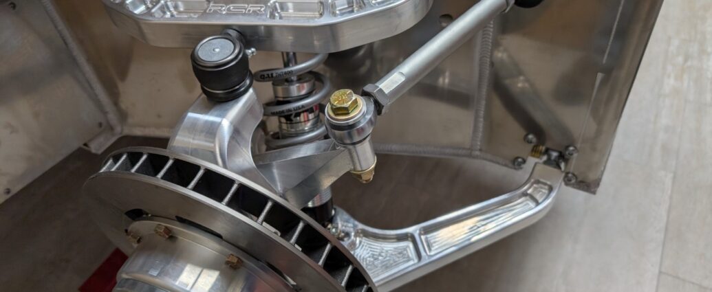
The success of your build will require positioning the suspension prior to finalizing your body mounting. The panels are all located around the position of the wheels. There are some common misconceptions that need to be understood to make the best of this process.
Wheelbase
The spec of the original design calls for a 95″ wheelbase. But no one identifies what it is after the front and rear suspensions were aligned. Caster immediately comes to mind as it positions the spindle center behind the theoretical wheel center. Then there’s manufacturing tolerances. This was the 1960s not current technology times.
The RCR system really sets up better when you accept the wheelbase will be around 94-1/2″. But even then, the body panels dictate more than you realize.
Rocker Panel positioning
To get the best wheel clearance, the front wheel well must be as large as the moldings will allow. The panel must be positioned as tight to the aluminum chassis as practical. On my build, I had to cut the flange off and reform it along the bottom edge as it would not set back far enough to allow wheel clearance when it turned in.
Rod End Adjustment
The suspension uses heim joints on almost all the joints. And there is no documentation on where to begin. I assumed the designer wanted adjustment in both directions and in the least engaged position, the threaded joint still must have minimum thread engagement. I built this chart to set the heims to a neutral position. From there, I adjusted as necessary to gain clearances or proper alignment
[wpdatatable id=1]
The “mid-point” dimension is the amount of space between the jam nut, threaded all the way on and the body the joint is screwed into (ie the control arm end).
- Thread the jam nut all the way onto the heim, till it bottoms out.
- Thread the heim joint into its socket until the space between the jam nut and the part matches the ‘mid-point dimension’. Since you need the joint turned to a certain angle, close is good enough.
Suspension Spacers
RCR must own stock in a flat washer company! Your kit will come with about 4-5 washers that serve as spacers on every joint. There are about 16 joints on just the front end. Do the math – that’s about 75 washers on just the front end. And there’s almost double that on the rear.
To put it as politely as I can, it looks like shit. I understand why it’s done that way – every car will be different and it’s impossible to know the exact spacer thickness needed.
I chose to make solid spacers for each joint. A couple of tips to make that go smoother
- It’s been determined that the kit sets up easier if the front suspension is moved as far forward as possible. Since every little inch matters, I machined the clearance washers that go on each side of the heim joints that go on the very front lower control arm socket. Space that arm as far forward as possible.
- When measuring for spacers, be aware they are about 1.375″ in diameter and will interfere with the radii on the inside of the suspension mounting sockets.
- On the thinner, forward ones, I sanded one edge off to make it ‘D’ shaped. Then put the ‘D’ to the top so it clears the radius of the socket wall.
- On the larger rearward spacers, I chamfered them about 3/16″ x 20 degrees. That’s enough so the spacer will bottom to the wall and not interfere with the radius
Comments are closed, but trackbacks and pingbacks are open.