
Skip to content
Ducting

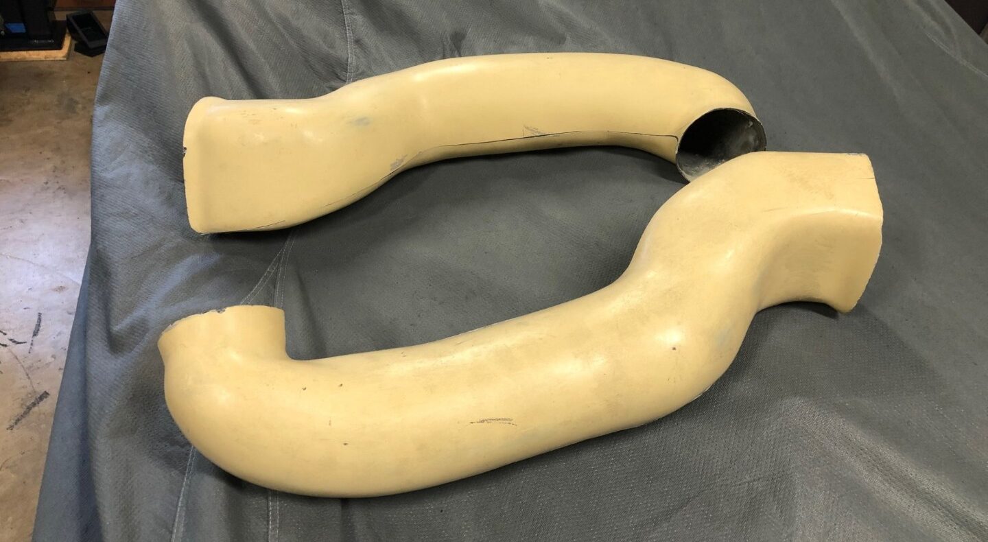
The fiberglass body of the GT40 is a relatively complex mixture of components. The build kits typically supply you with the outer shell pieces: Spider, Rockers, Doors, Front and Rear clips. The better suppiers add the inner shells to complete the clip or interior.  Yet few if any address the inner components, the ducting that routes air from the NACA ducts to the interior, the rear pieces to route air from the side scoops to the brakes, engine or oil coolers. These are not only needed to be period-correct but they also are a function component of the car.

Years ago, Bill Hough had these as part of his offerings. With Bill now retired, no one has picked up the supply so we are left to our own devices.

Fiberglass is relatively easy to mold, that’s part of the beauty of it. I’ve outlined how I built the front NACA ducts, the rear brake ducts and the oil cooler ducts.

FRONT NACA DUCTS

The front ducts get their name from studies done back in 1945 by the National Advisory Committee for Aeronautics (NACA), the precursor to NASA. The concept is a recessed inlet rather than a scoop to get air into an aircraft without creating additional drag.  If a scoop projects out into the airstream, it takes some amount of horsepower to overcome the drag its shape generates. If the inlet doesn’t project into the airstream, it doesn’t create drag and the horsepower can be used to do something else, like go 200+MPH in the Mulsanne straight.

The front clip, depending on the model you are replicating has two or three ducts.

    • The MkIII did not have any NACA ducts.
    • The MKII and IV have two smaller ones up front direct air into the cockpit for driver cooling (Original GT40’s didn’t have air conditioning.) 
    • The MkI and MkV also have a larger NACA duct, centered under the front windshield which directed air into the front demist pocket for additional cockpit ventilation.

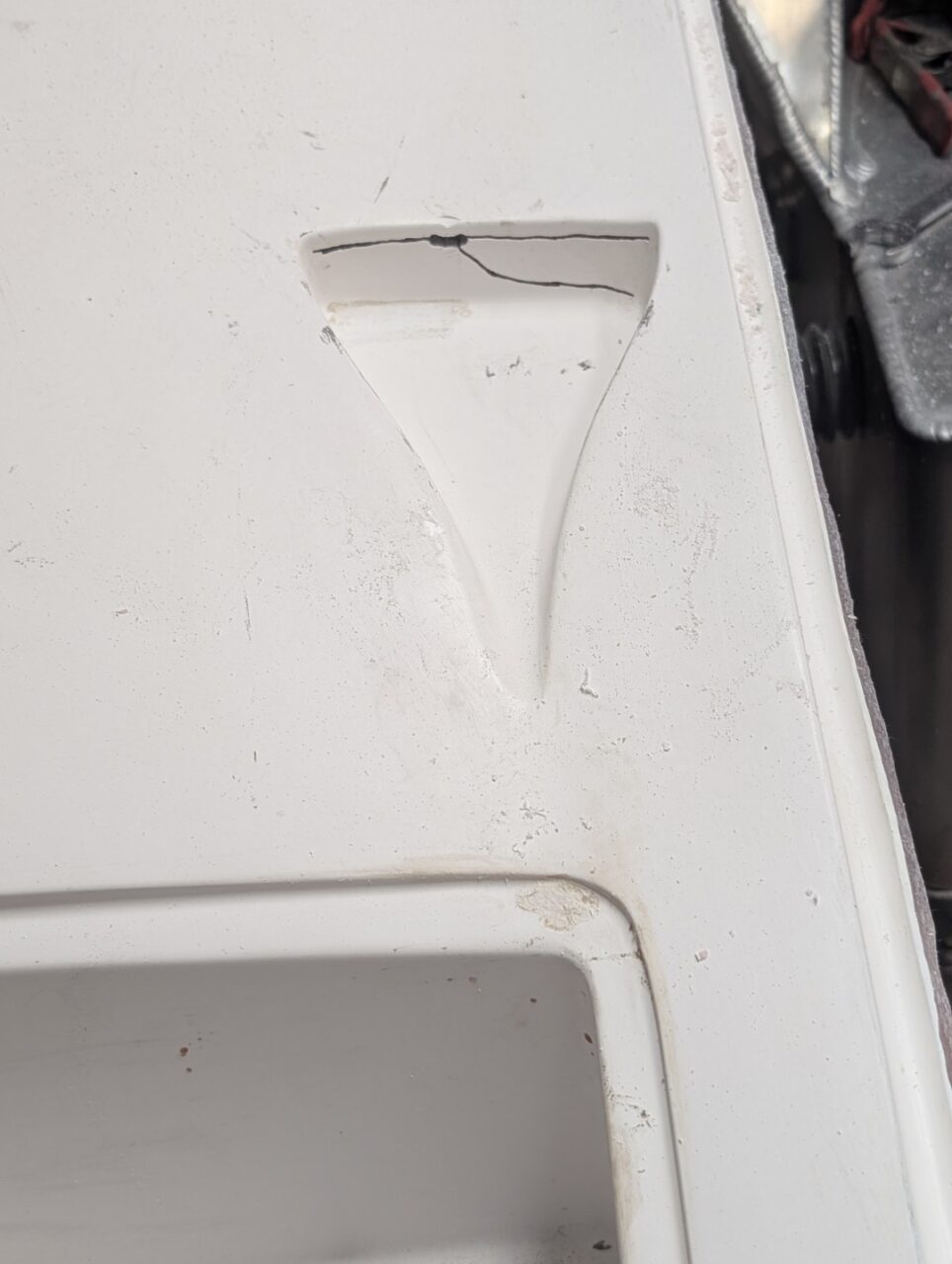
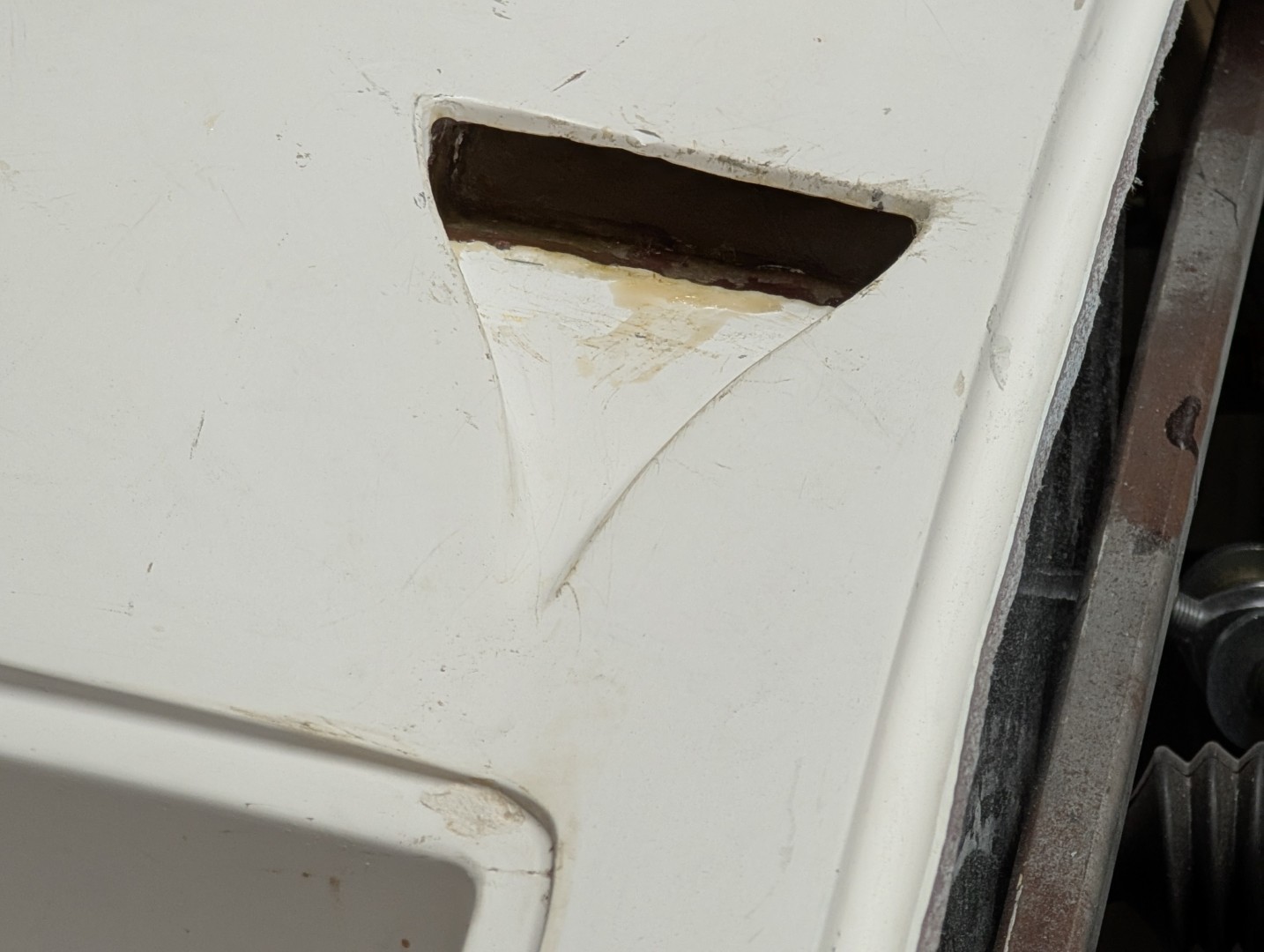
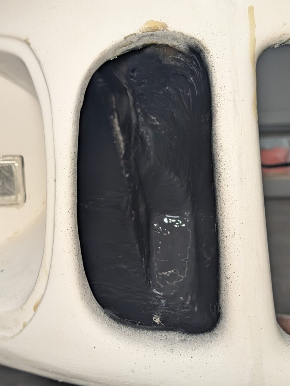
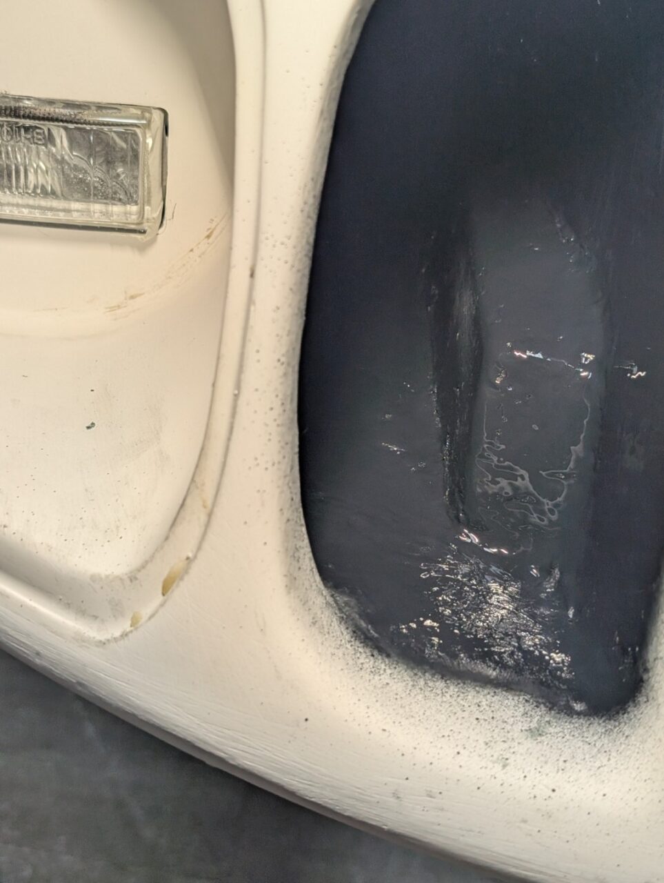
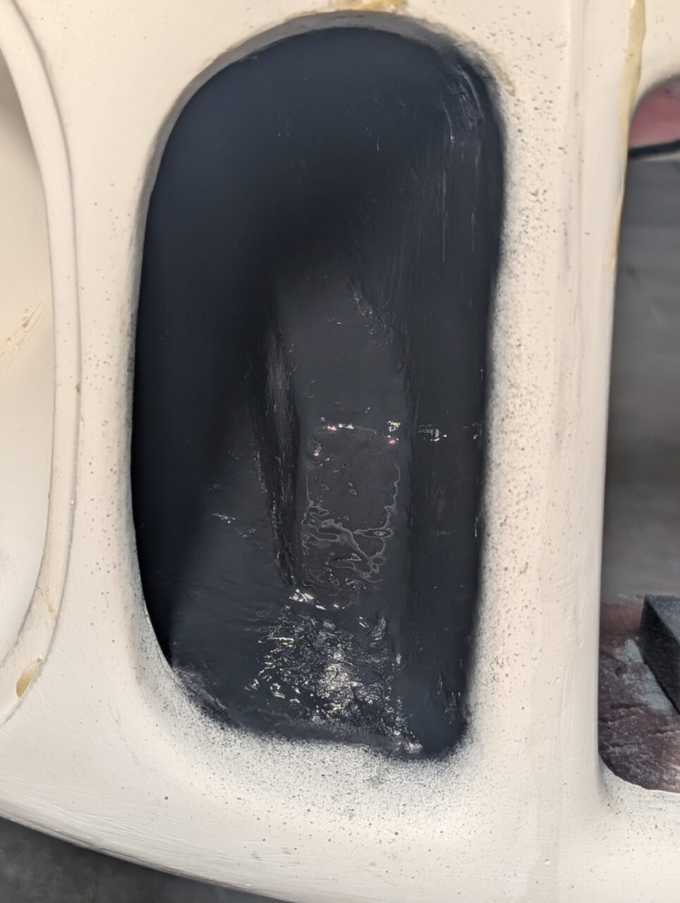
My RCR body came with the proper ducts molded into the clip, however they were not cut open nor was there any ductwork to route any air that may enter the duct.

Front smaller ducts

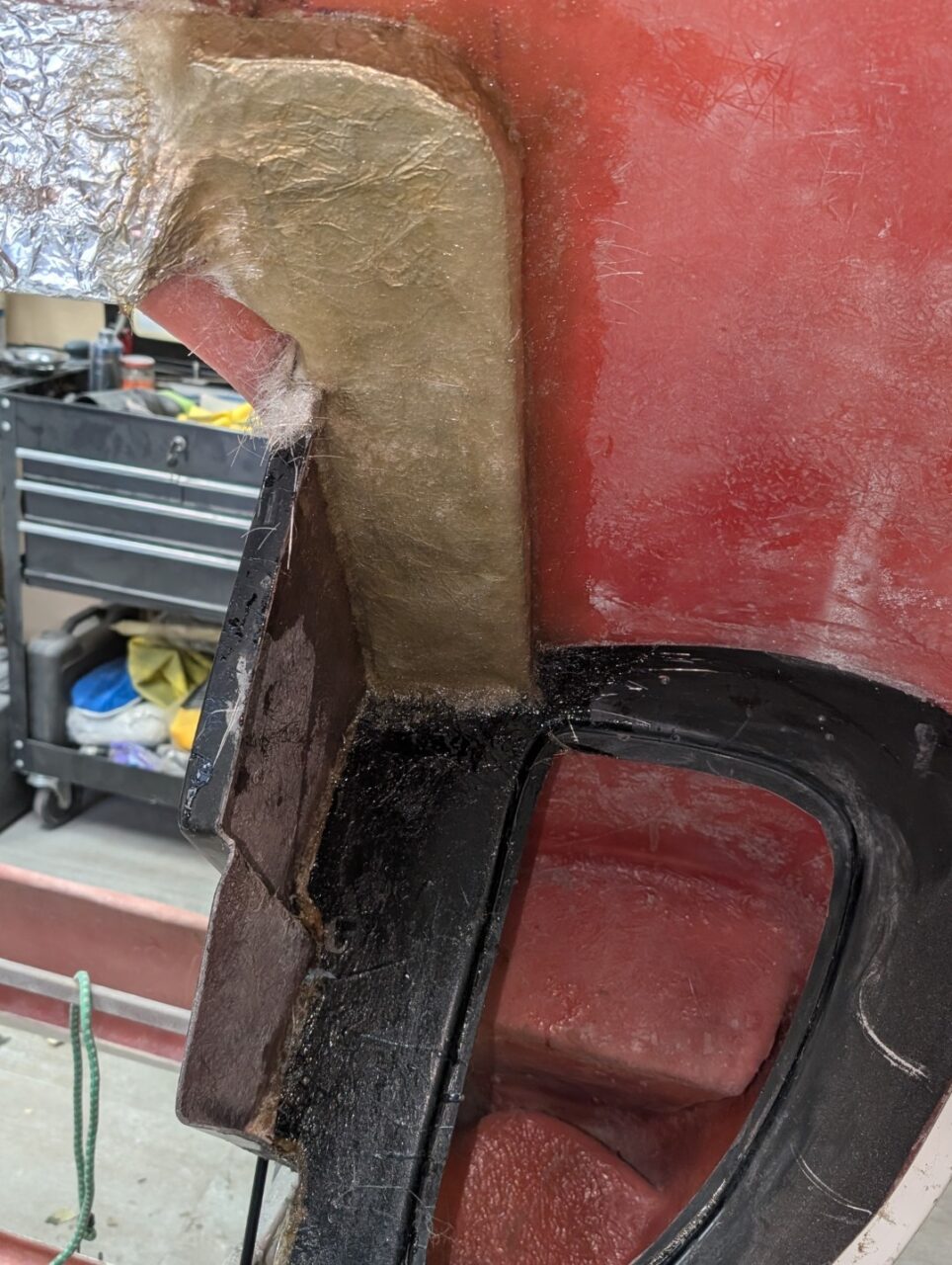
Cutting the ducts open was not a big deal, but they came the construction of the ductwork to get it into the cockpit. My first attempt was to use brown Polyisocyanurate foam. It is not attacked by the polystyrene compound of fiberglass and could be chipped out after the fiberglass sets. However that became easier said than done. 

I then elected to model the necessary shapes from eGlass, the fiberglass used to make circuit boards. It is about 1/16″ thick and can be glued and built up with the fiberglass materials we commonly use. The model provided the smooth inner surface for the duct and was covered with additional layers of fiberglass to add to its strength and stability

The duct will connect to an air valve on the front of the chassis. This will be detailed in another section. It is a similar but smaller version of the valve used in Cobra footbox vents.

Center NACA duct

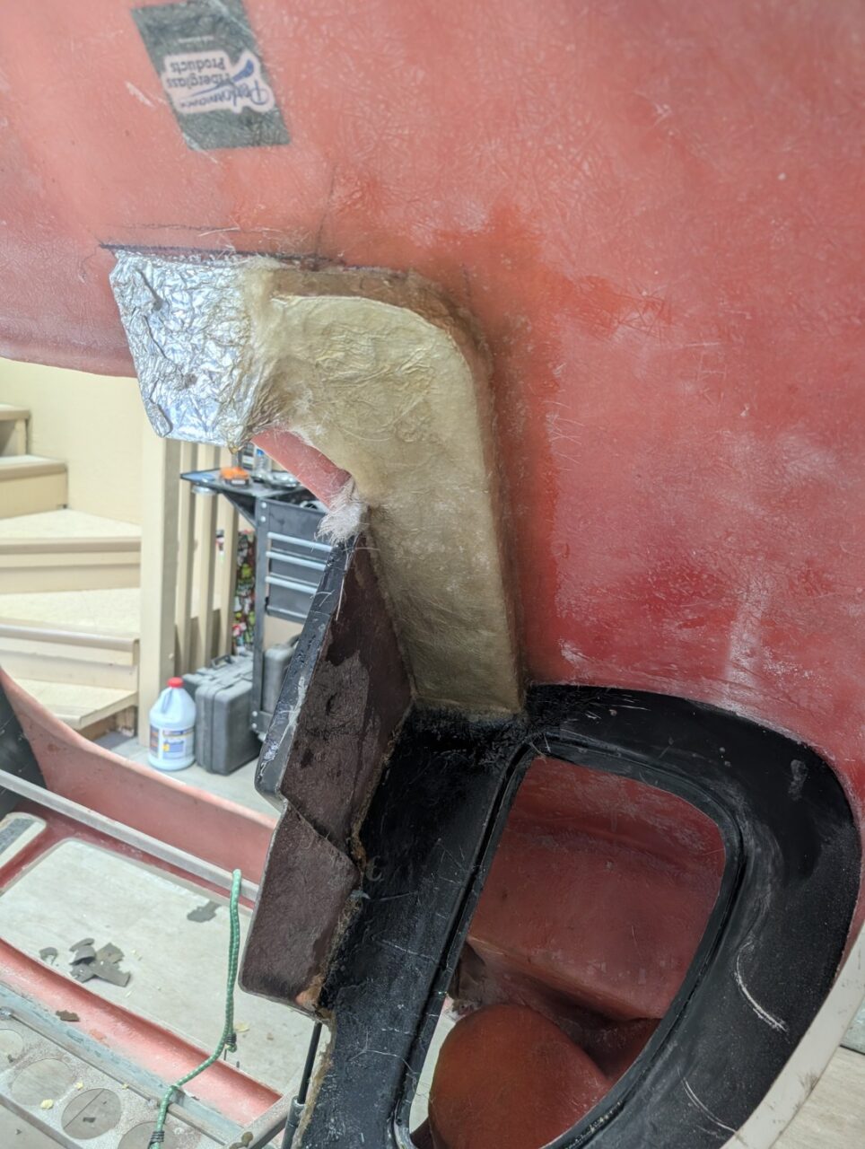
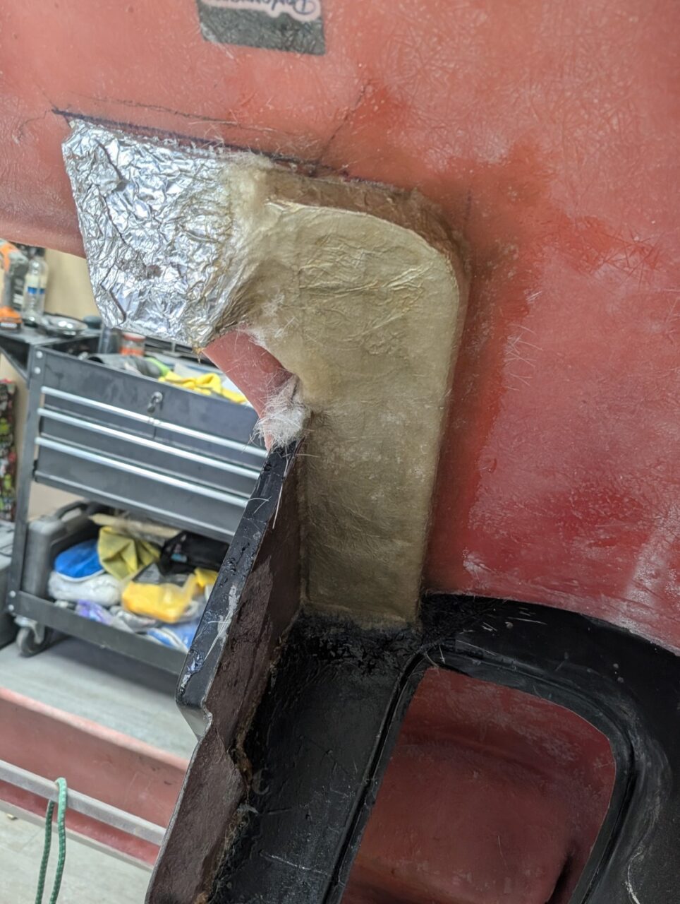
The center duct is not opened when the clip is molded. There is only about 1″ depth when it is cut open so any treatment is going to be visible.

  • Some builders have routed air thru side exits over to the front duct channels. This seemed to be a lot of work and probably little to no flow from the opening. 
  • Opening the front clip to use it as it was designed presented another challenge: How to keep rainwater from entering the cockpit. There isn’t much room to build a baffle and drain system.

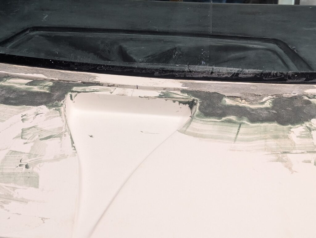
I chose to open it thru the edge of I have yet to determine if it will appear as I want it to. To be addressed later – keep your fingers crossed.

Rear Ducting

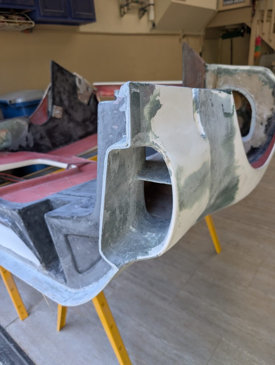
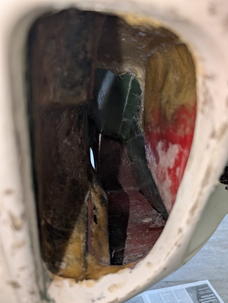
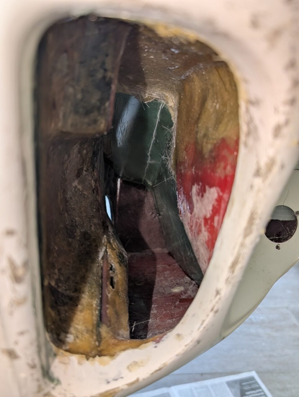
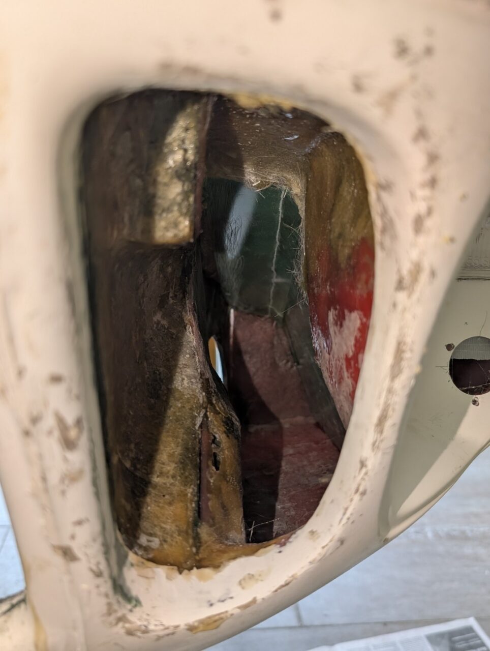
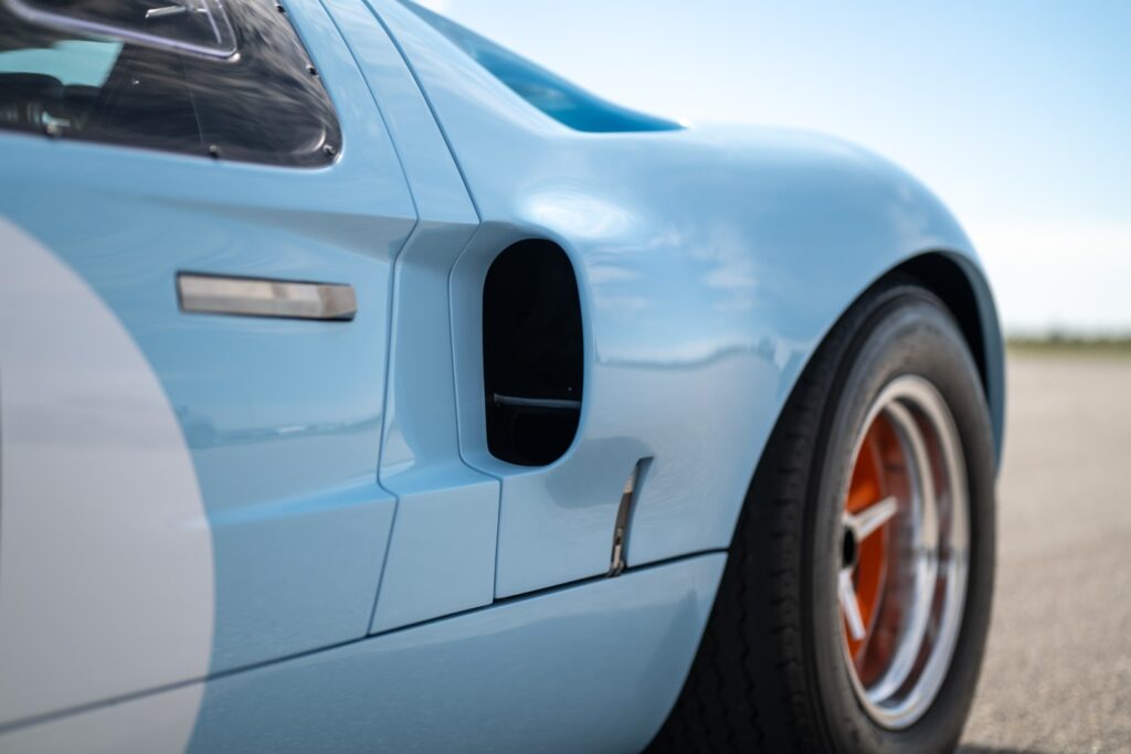
If you look into the scoop on the side of the GT40, you will notice a horizontal splitter in the opening. This is the leading edge of two internal ducts.

  • The lower one does a quick 90 degree turn and feeds thru the sidewall of the inner liner. It directs air to the oil cooler mounted ahead of the tire.

The upper one routes the air up and into the engine compartment, where it then feeds into the rear brake cooling duct. There are multiple versions on how the air is directed once into the engine compartment.

Since I don’t have immediate plans to run the car in a 24-hour endurance race, I felt engine compartment cooling would be a little more important than rear brake cooling. I modified the inner wall and have the discharge directed towards the exhaust collector area.

Lower Duct

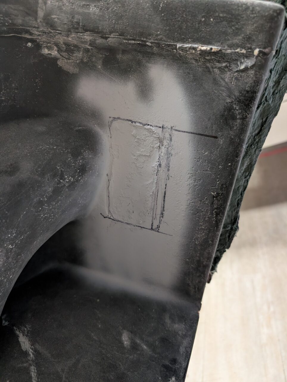
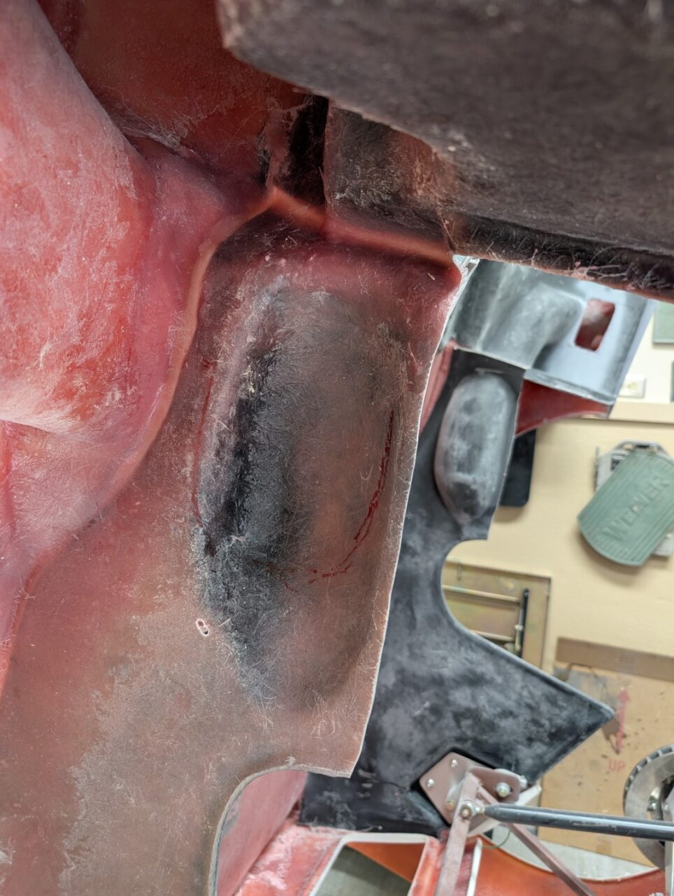
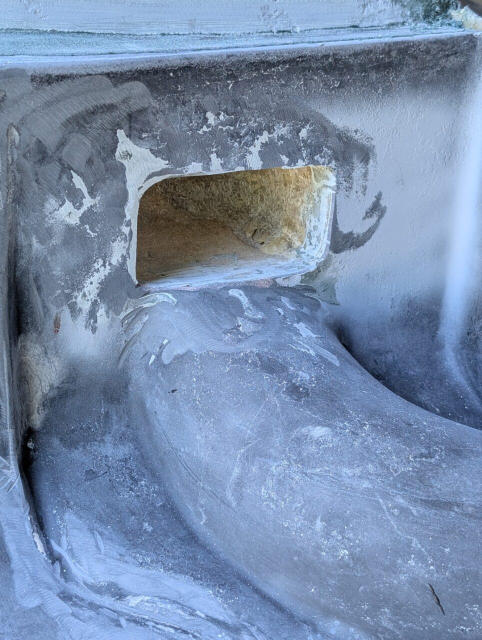
The first part of making this duct is opening the outlet on the panel wall. If building an RCR MkI, you will note a faint rectangular outline of the opening. With the opening in place, the plug may then be made to fit the body. Note that both sides are not only different due to the RH and LH but dimensionally, there is also a difference. Probably due to the body shape at that location and the position of the inner panel.

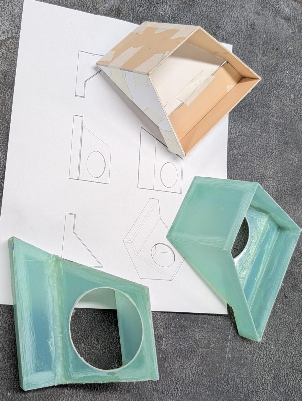
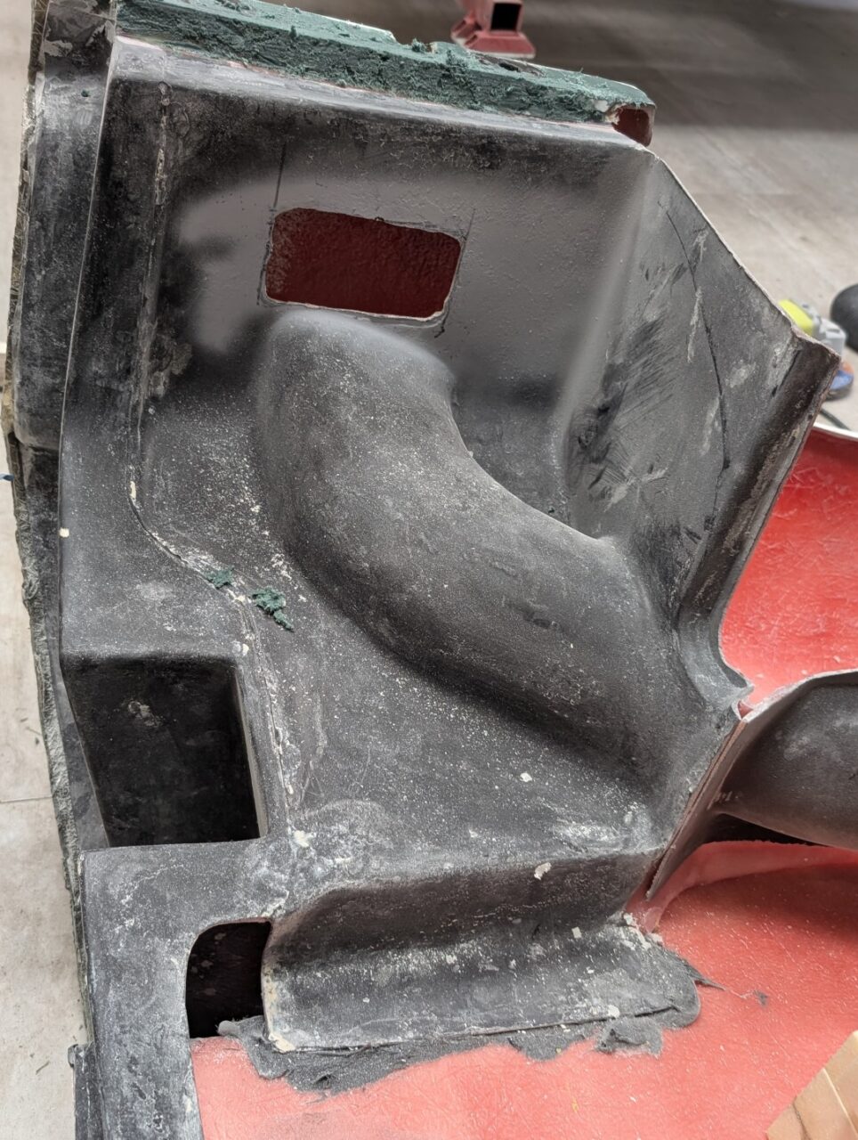
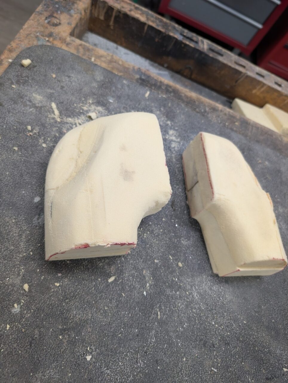
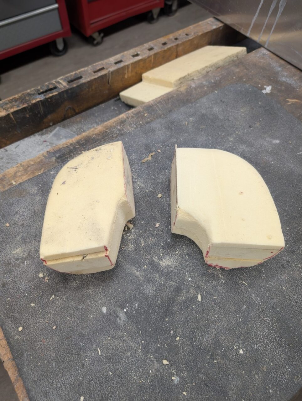
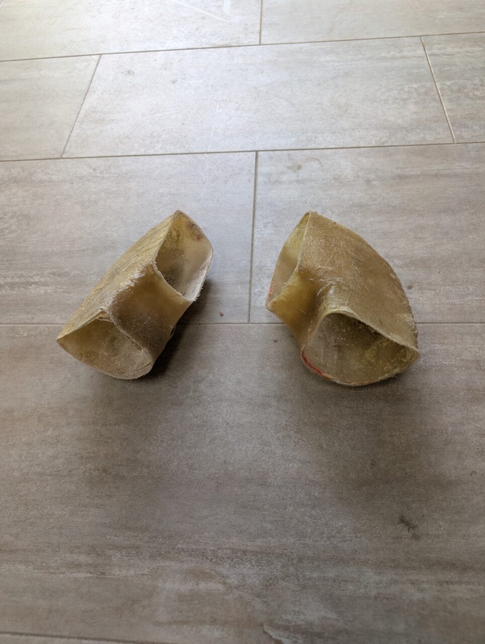
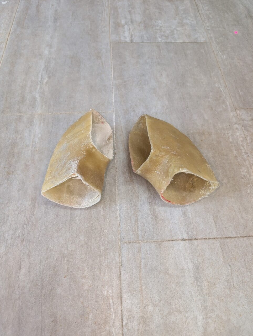
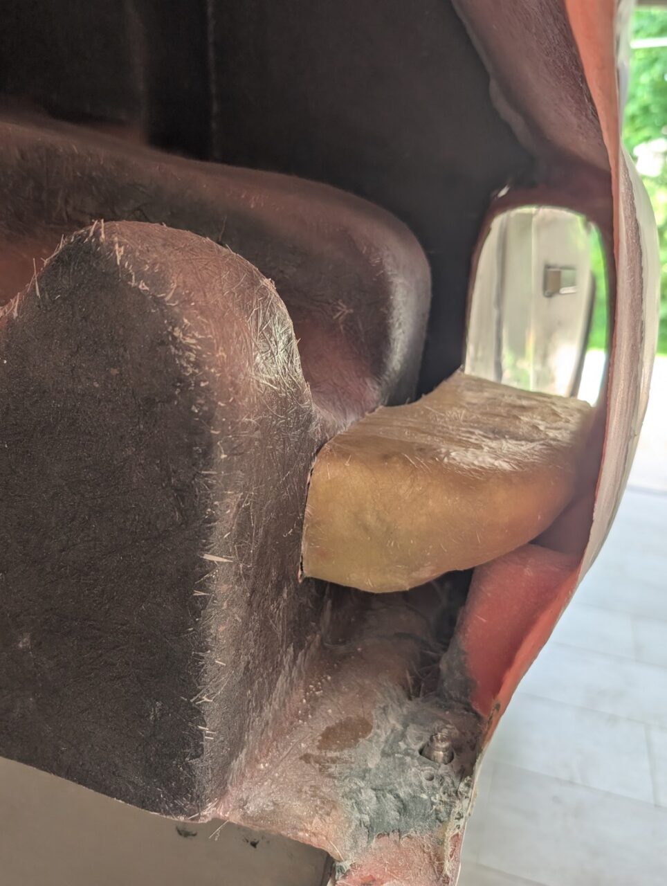
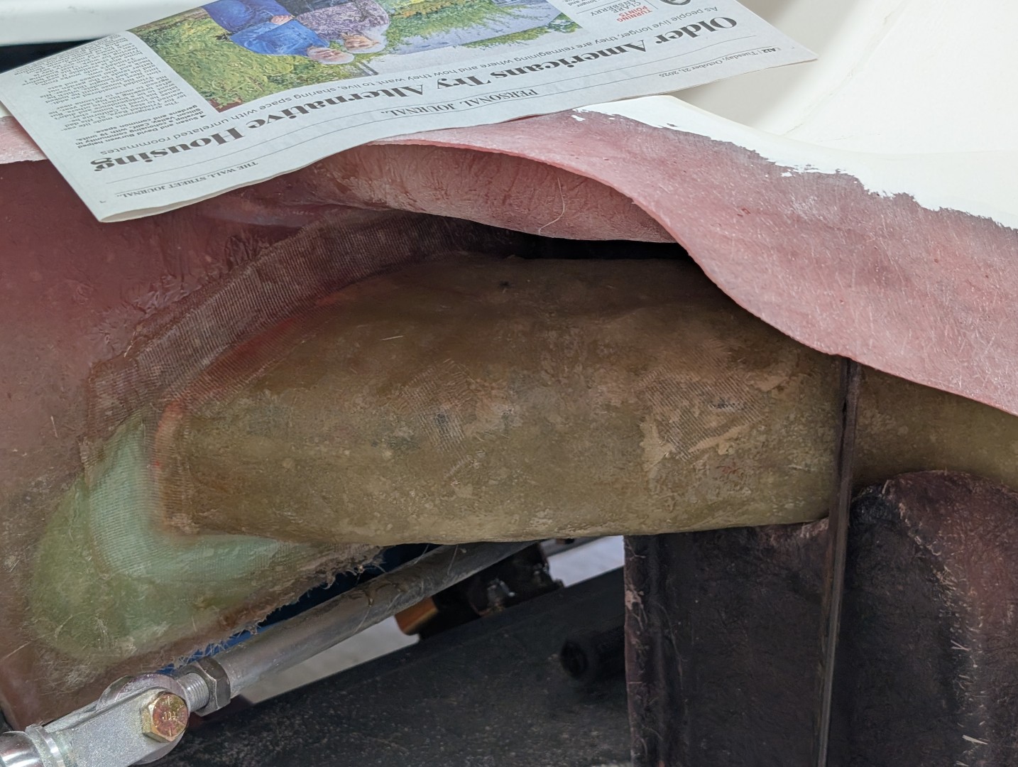
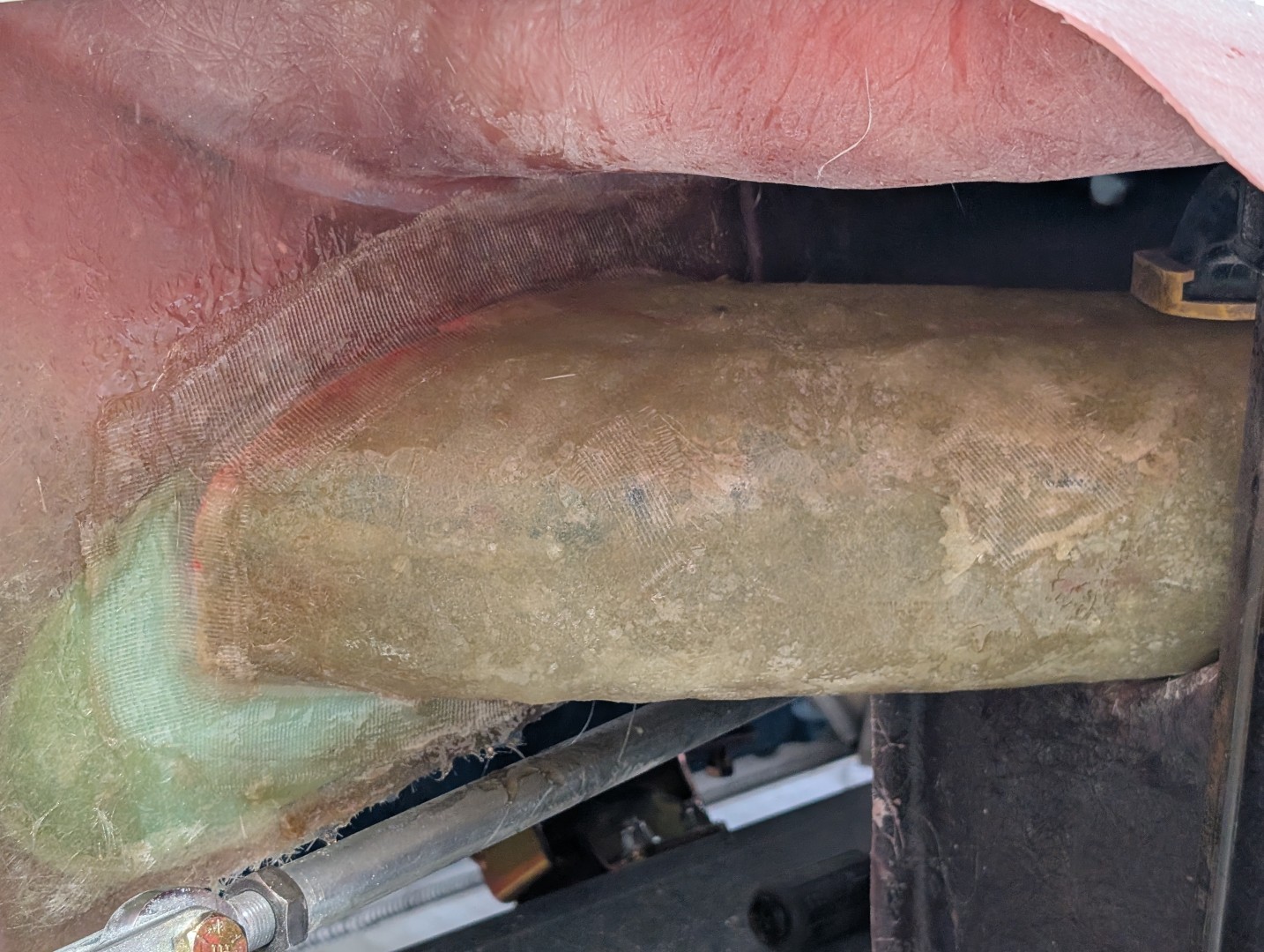
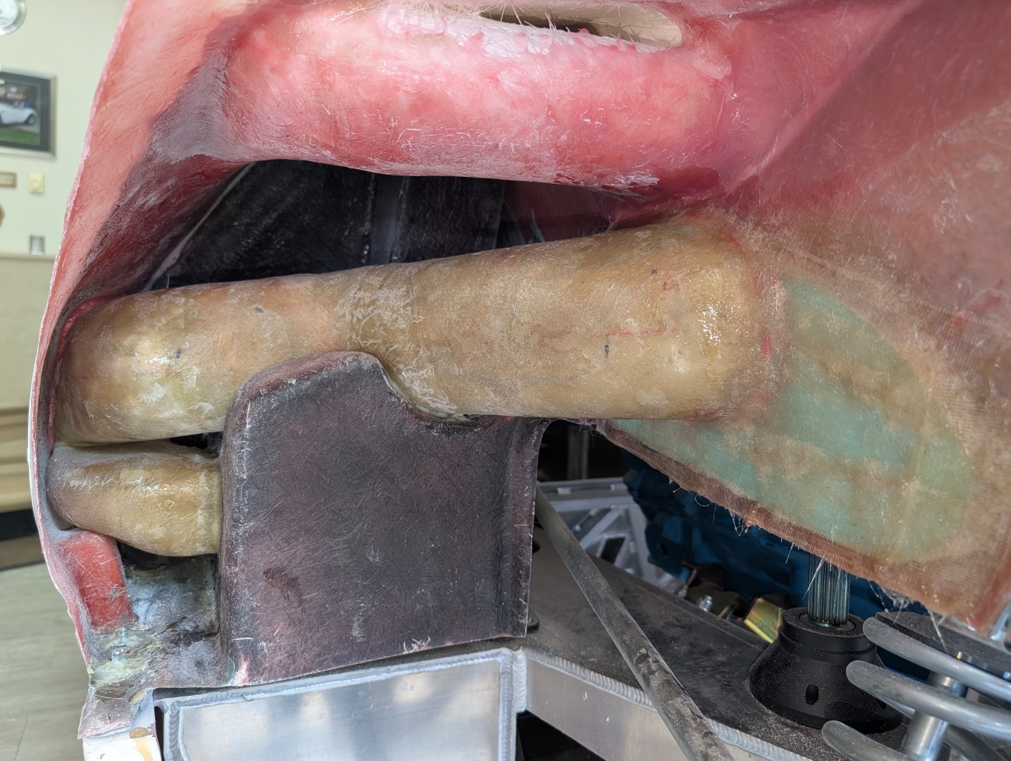
The lower duct is a relatively simple mold, carved from brown (Polyisocyanurate (PIR)) foam. Shaping it is a matter of making the rough plug that fits the openings in the body, then shaping it to the finished shape. The foam is easily modeled using a keyhole saw, box cutter, and coarse sandpaper. Once shaped, it was then covered with a couple of layers of glass mat and resin. When cured, the brown foam was chipped out of the part and the inside cleaned.

The molded part is then positioned inside the body and ‘glued’ in place using MMA adhesive in a few locations. Once the adhesive has set, the edges can then be faired to the body using polyester resin and strips of fiberglass.

The upper edge in the outer scoop is left unfinished as it is mated to the upper duct.

Upper Duct

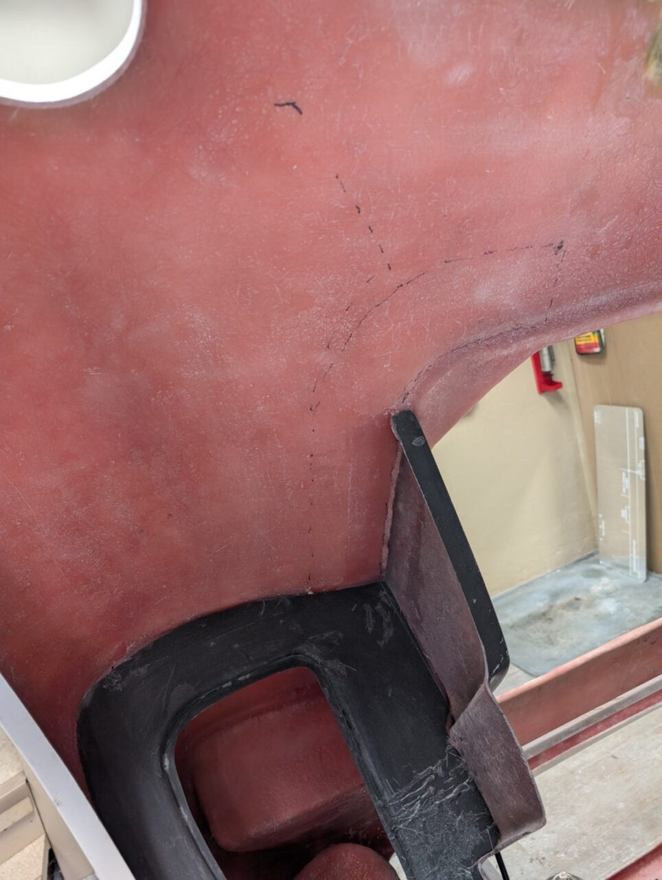
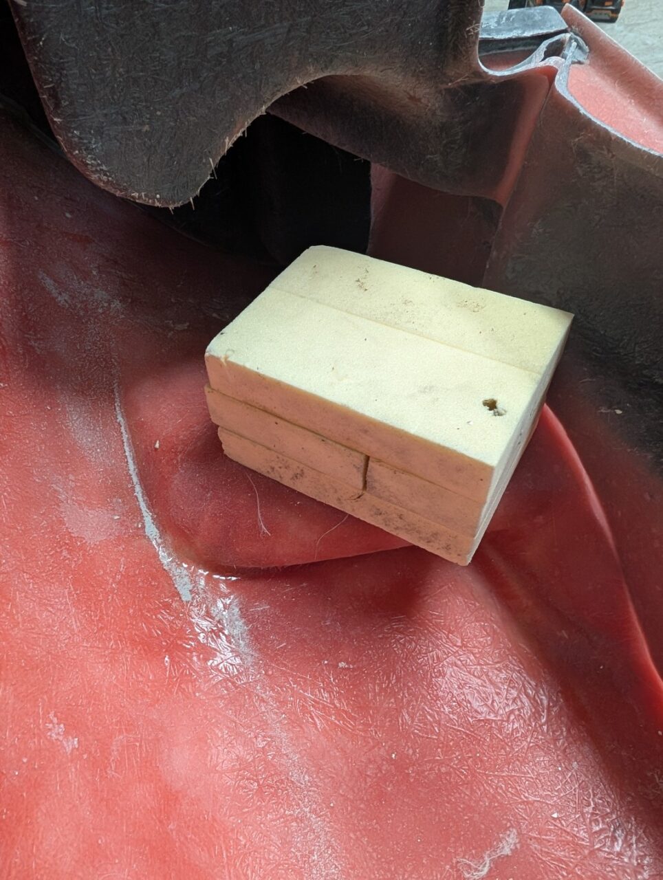
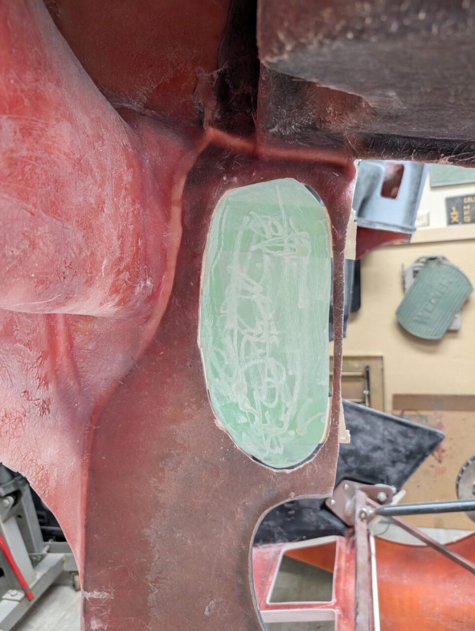
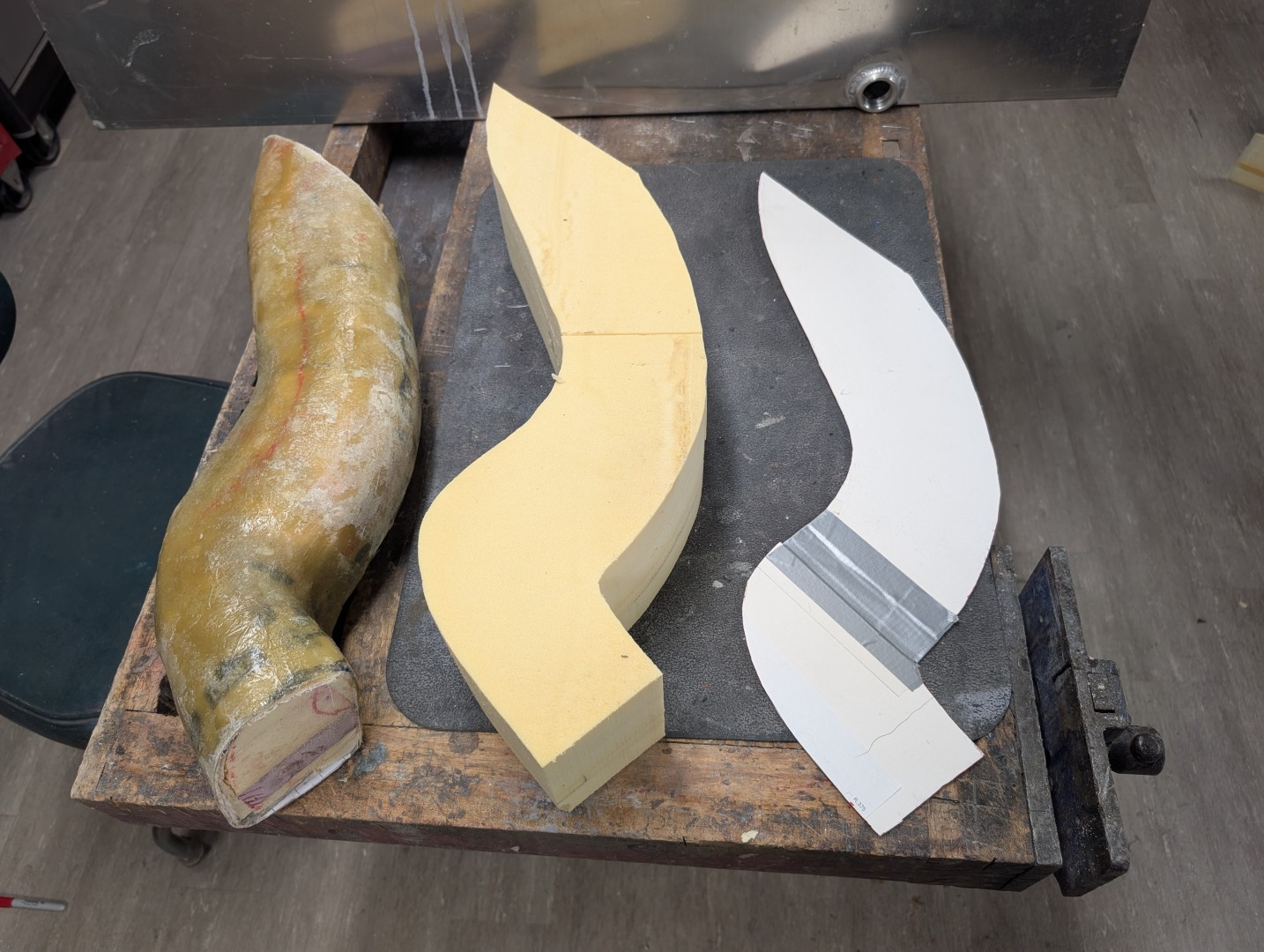
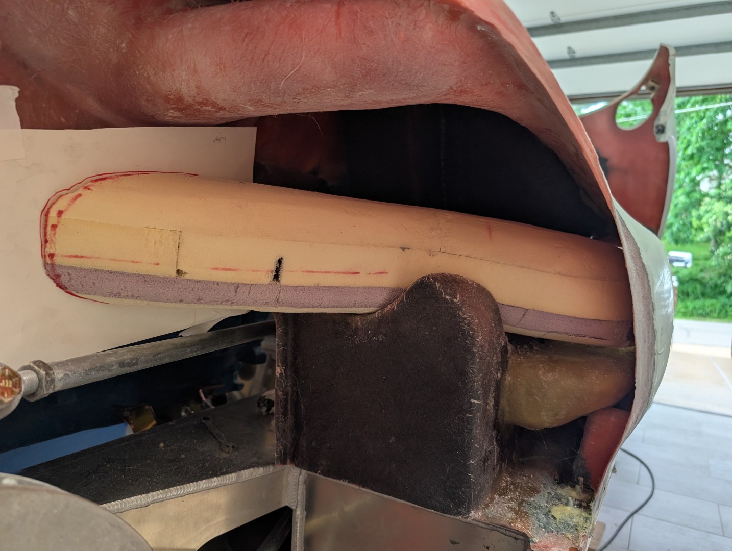
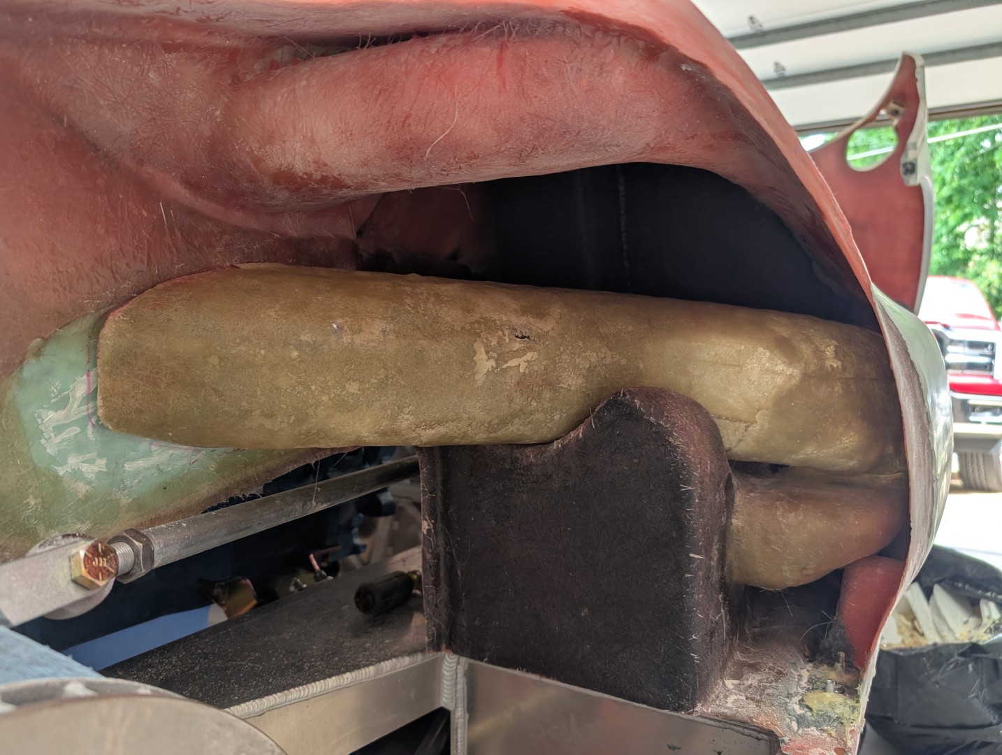
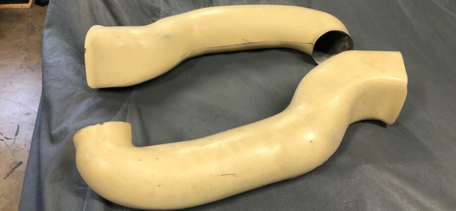
The upper duct becomes a little more complicated. Its size, the fact that it is pretty much round its whole length, and the curvature of the shape make it a difficult model to make. I decided to route the air into the engine compartment rather than duct it to the rear brakes. I cut away the curved section of the inner panel, which created an oval-shaped opening in the wall. I then laminated sheets of foam till the necessary size was made, then cut the curvature needed to fit the body and the openings. After the round shape was established, I then concentrated on fitting it to the body and openings. This was complicated by the fact that the piece requires “snaking” into position. Remember the size will grow about 1/8″ on each side when the plug is covered with fiberglass. It was then covered, and the plug was chipped out to form the duct. It is a very messy process, and you will have little foam pieces everywhere.

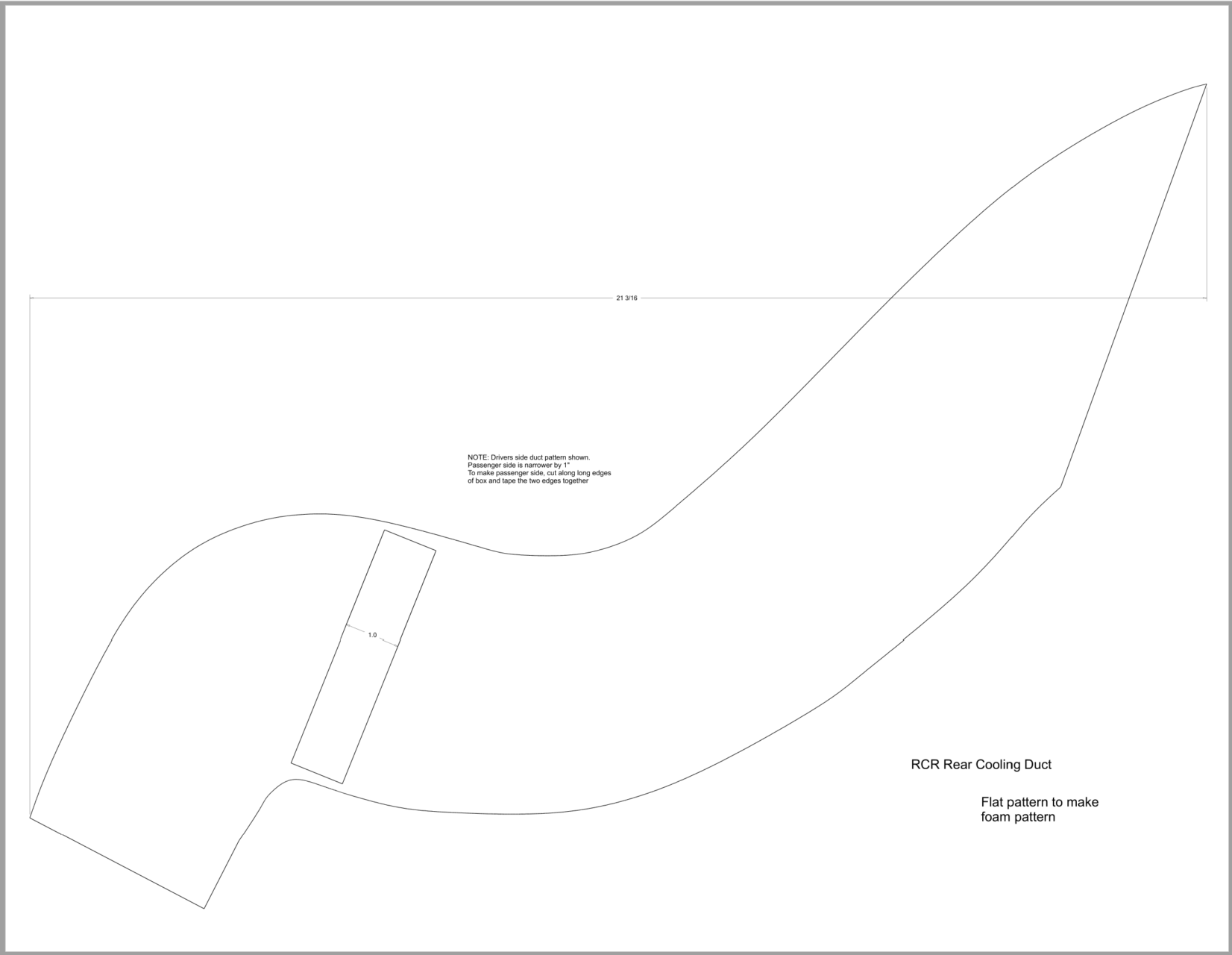
To help the next builder, this is a pdf of the shape I started with. You can print the PDF at full size, paste it to the foam sheets and be ahead of the game by at least 10 hrs. Note the two sides are slightly different. You should check the pattern against your body. The molds are the same, but where they get glued into the body varies from car to car.
Front Brake ducts

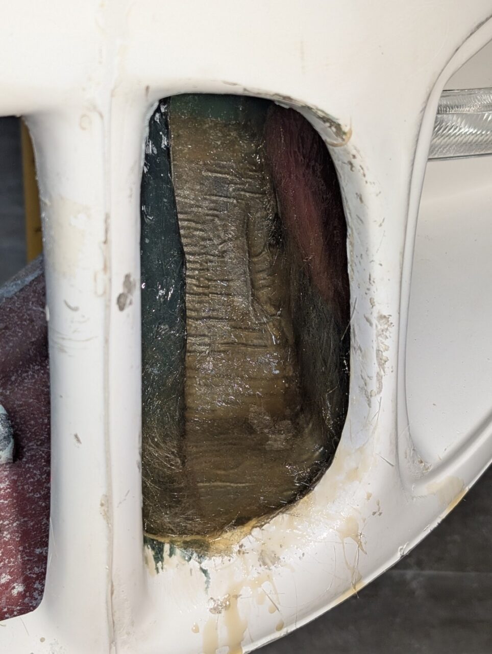
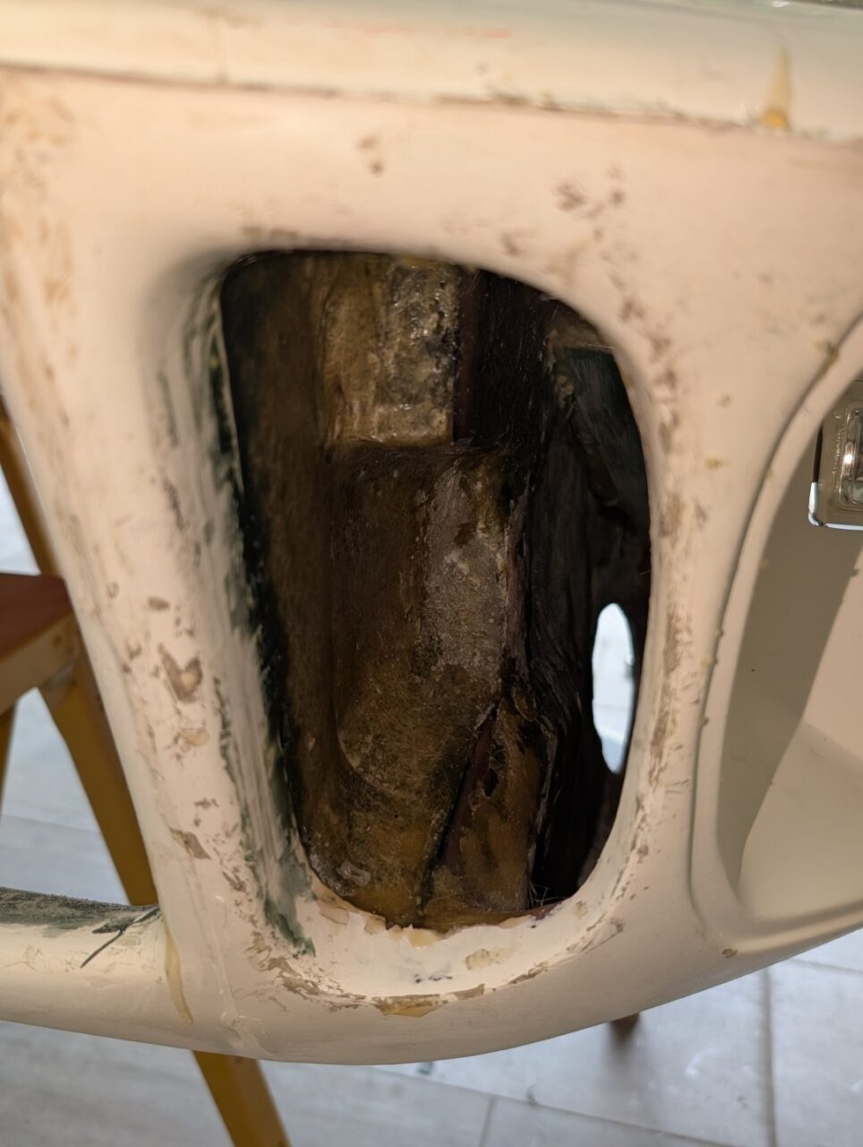
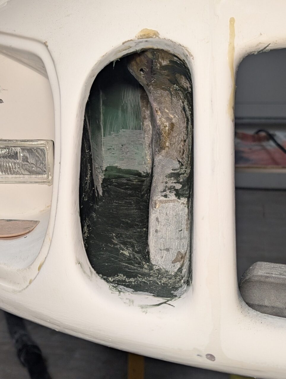
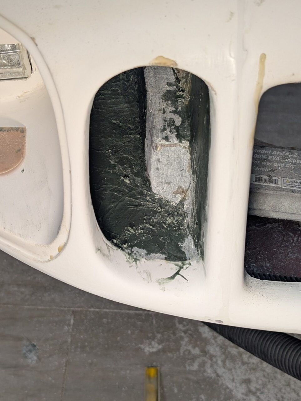
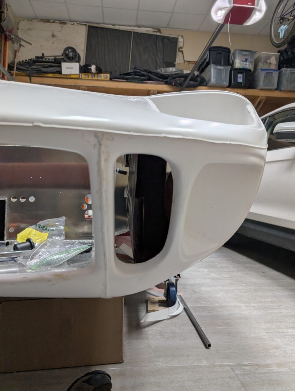
The nose of the RCR MkI has the correct duct openings, but they do not replicate the duct work or original appearance.  Myu opinion is this will adversely affect the presentation of your build. Something had to be done about this.

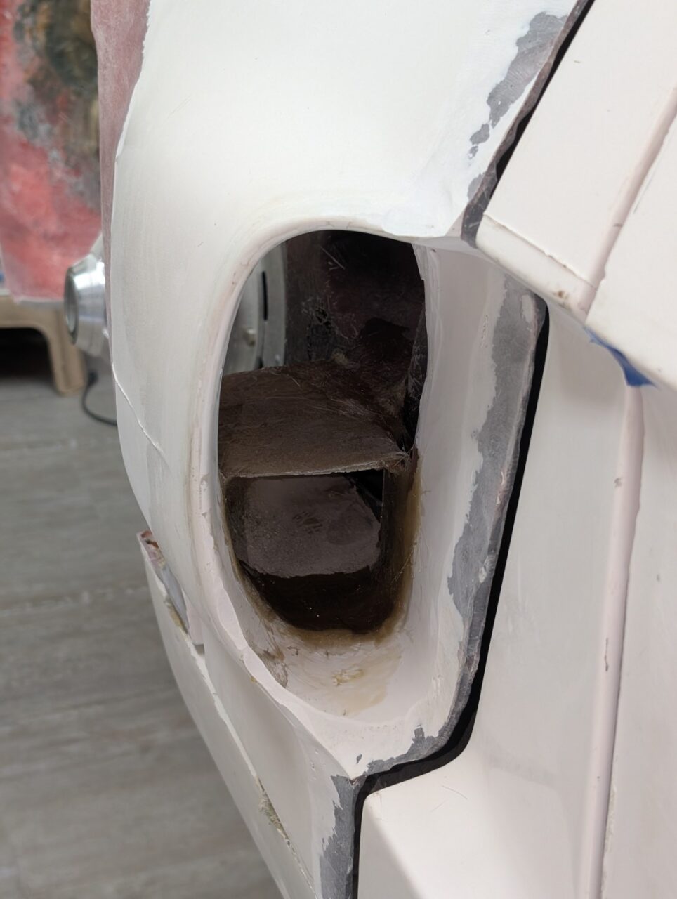
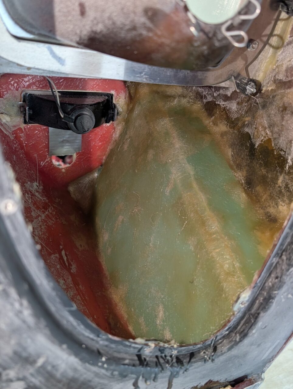
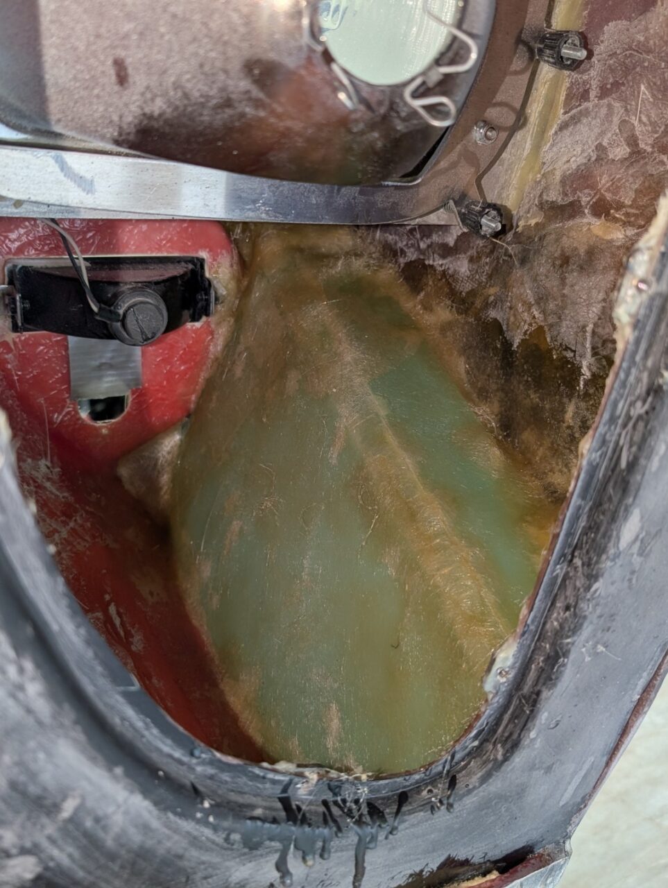
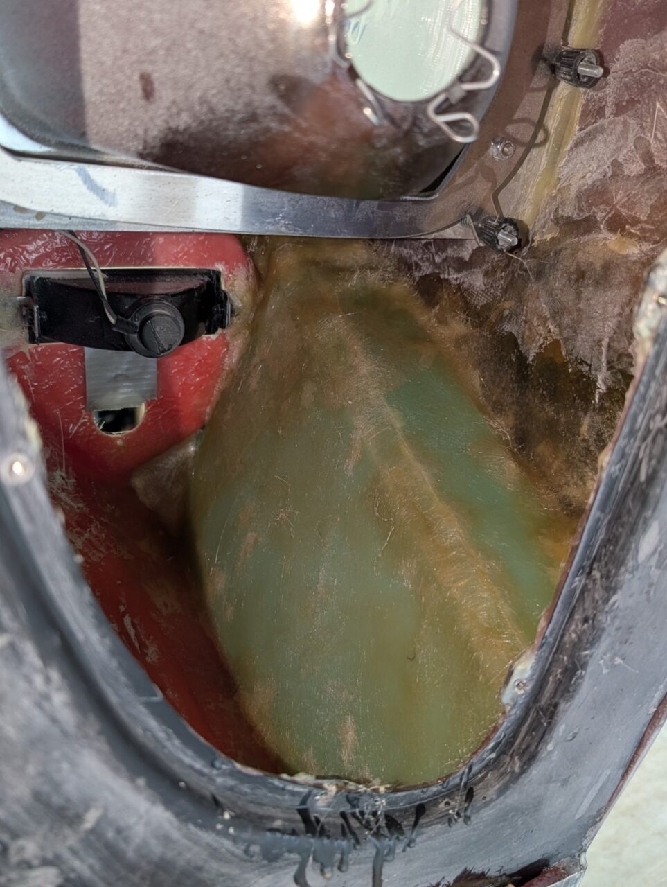
The front brake ducts are a true test of your arts-and-crafts ability. The openings in the nose are there and the transition opening on the inner fender liner is outlined. Other than that, they don’t exist. If left alone, air (along with rain, bugs, leaves, road trash, small children) will get sucked into the headlight/parking light enclosure. My pivoting clamps and front frame had to be considered in the arrangement.

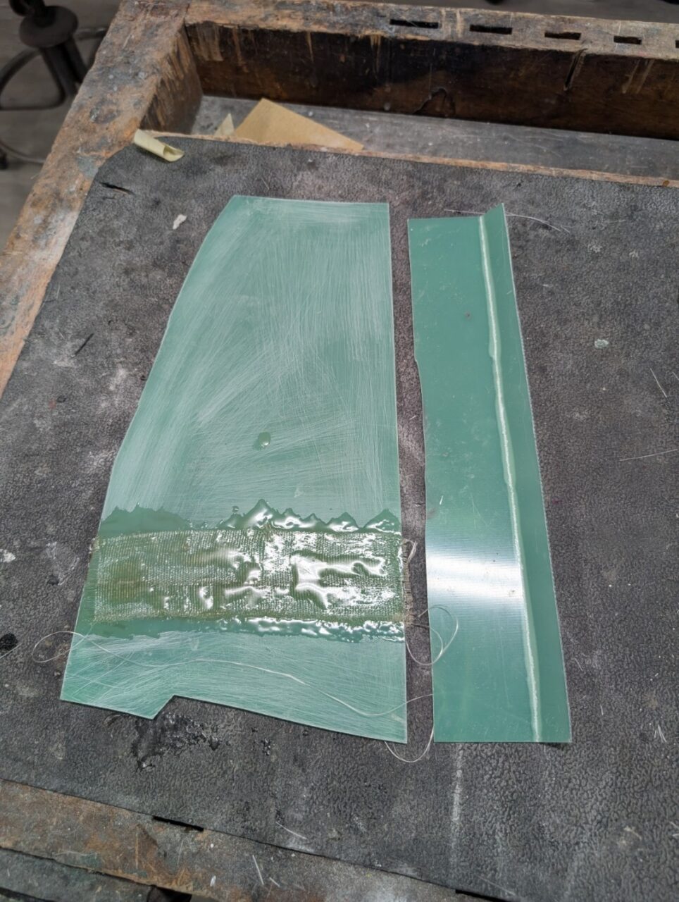
The shaping was a combination of pieces cut from mat board, 1.5mm G20 fiberglass panels cut to specific shapes and the front clip itself. The inside of the clip has the headlight and parking light recesses. These served as part of the duct wall, the task was to make a wall that would direct the air to the rear 4″ hole and keep it out of the rest of the lightbox area. I cut a piece of G20 board to 13″ x 2-3/4″. I scored the long edge at 1/2″ and then bent the edge about 45 degrees. This would form the top of the duct. I then cut a piece of G20 to about 13″ x 6″. The rear edge had a slight angle on it to fit the rear wall and the front edge had about a 1/2″ notch in it to fit to the headlight recess. I fastened the two pieces together with a couple pieces of duct tape (removed later) and then glued in place with MMA adhesive. Don’t forget to rough up the G20 on the outside where it will get bonded with fiberglass to the body. Please don’t ask why I am including this reminder.

Once the adhesive has cured, a layer of glass cloth was placed over the panels and resin applied to form it all into one piece. When cured, the balance of the duct is finished from the front opening.

I cut and bent a piece of mat board, 10″ x 2-1/2,” and covered it with duct tape. The tape would serve as my mold release. I then positioned it into the front opening, taping it to the rear part of the duct. I used a triangular piece of matboard and duct tape to finish the mold shape to the parking light recess. With all this in place, I then added strips of fiberglass and resin to finish the duct to the nose opening. Once cured, I could reach in from the back and remove the cardboard and duct tape. I laid down a couple of layers of glass cloth.

I then used kitty hair to make a smooth transition from the nose opening to the glass duct. It seems so simple now, writing about it; however, this took the better part of two days to do the two sides.

Sorry the pictures are so crude – it’s a messy process and doesn’t photograph well.
More
articles

Designed using Unos Premium. Powered by WordPress.