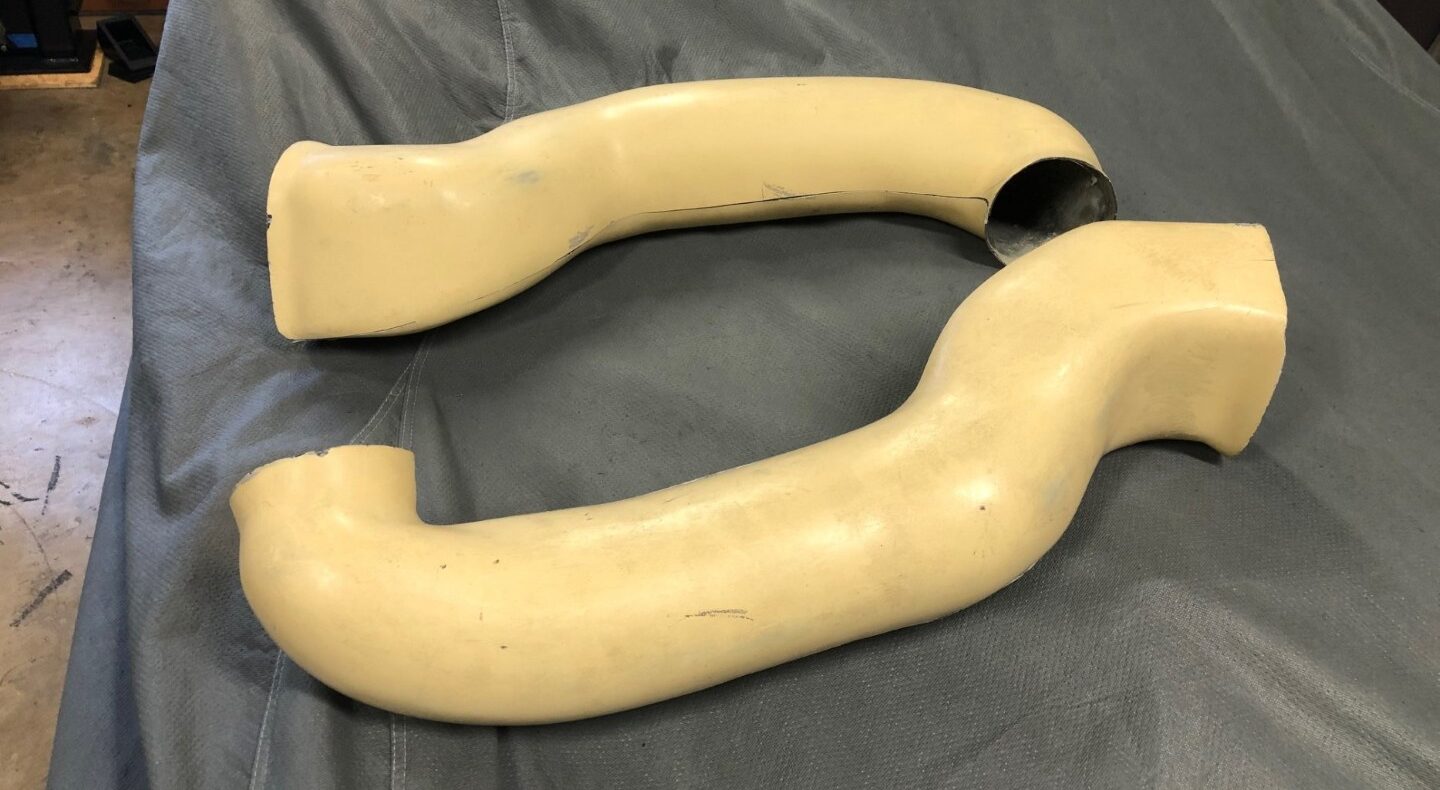
Straight end, curved end, angled end - Oh, my!
The entire body fitting process begins with the front clip. Once it is centered over the front wheels, you can begin to position other pieces. Cool, but where does the front clip get positioned? It is a combination of the rocker panel, front clip wheel opening and front wheel position. Some comments to show the interaction:
- The front suspension/wheel needs to be as far forward as possible. Your kit probably came with the tapered spacer and a couple washers between the heim joint and the front lower suspension socket. You want the minimum amount so ditch the washers. (Also, check that the aluminum tapered spacer back edge is relieved so it fits flat to the wall of the socket. As produced, it typically doesn’t fit flat due to the radius between the socket walls and top.
- The front clip wheel opening gets centered on the tire. But the two sides are not symmetric and will require some fiberglass work somewhere in the future
- The rocker panels upper edge needs to match the clip wheel opening edge but also needs to be as much to the rear as possible, or the wheel will rub when turned outward.
- The wheel alignment needs to be approximate since ride height, caster and toe affect the location of the tire in the opening.
It is a balancing act between all these pieces. It does take a lot of playing/adjusting til you get it where you want it.
NOTE: You’ve probably already read the wheelbase of the GT40 is 95″. When the RCR GT40 was cloned, it came from GT40 P/1008. Whether due to accidents, modifications or wheel alignment, the clone comes in around 94-1/2″. You won’t be able to get the rough layout to 95″, the pieces of body and chassis won’t allow it.
Ok, on to getting it together.
Front clip, rough position
With the front clip in place, you can then position the rocker panels. If using the factory ‘bobbins’ slide the front clip on till the wheel opening is centered over the front wheel. I chose to modify the front frame and use a pivot system. You can see details of this here. If you’ve done similarly, adjust your pivot till the front wheel opening is centered on the wheels.
The RCR instructions show a 35mm spacing on the face of the spider to the edge of the spare tire well. Fran told me to take this as a rough estimate and not a required dimension. They’ve learned the wall of the tire well is formed by hand and is not precise enough for an absolute measurement. Mine came in around 33mm.
Rocker Panel, RH vs LH
There is a RH and LH side and it gets confusing which goes where. Don’t assume when your car was delivered, the correct rocker panel is on the correct side. I learned mine were reveresed. Phone calls to RCR had me totally confused, I was told the straight side goes on the front, curved side on the rear. I knew the lower edge of the front of the spider could come into contact with larger tires. When I put what I thought was the straight side in, it wouldn’t match any of the pictures of what others had done.
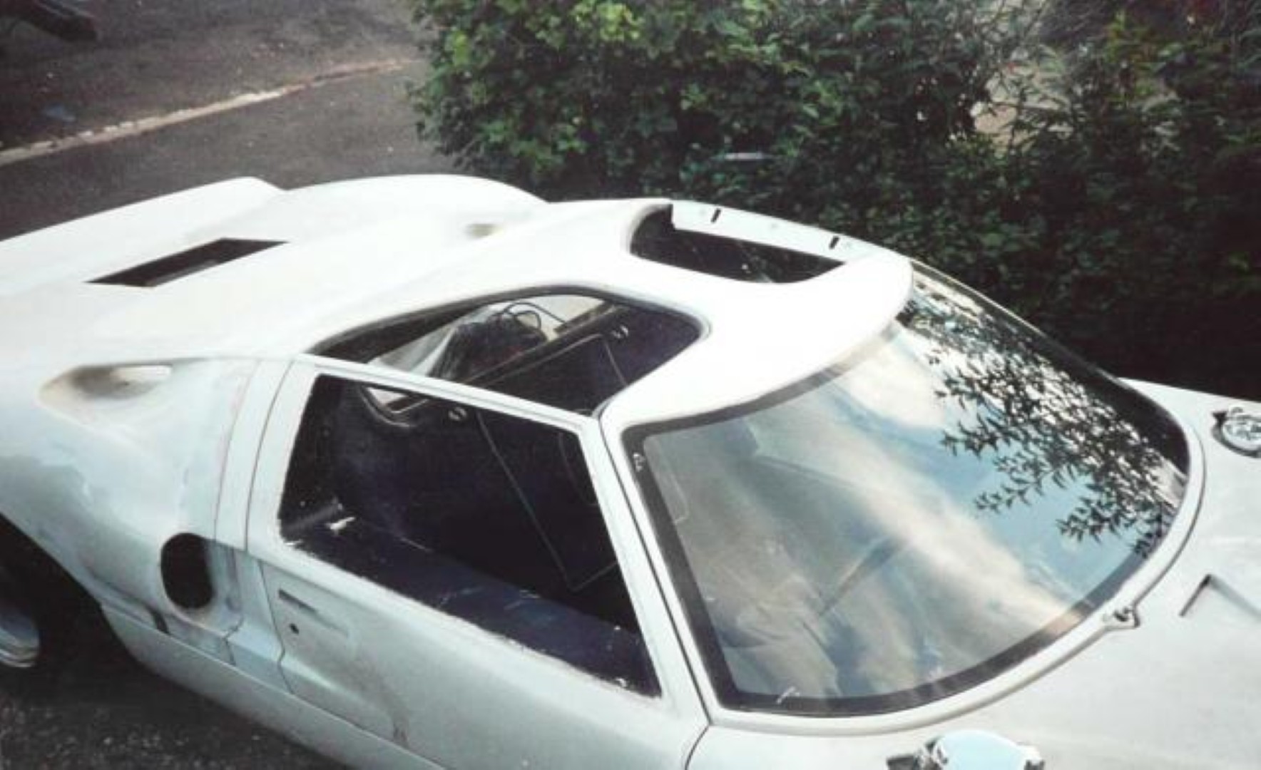
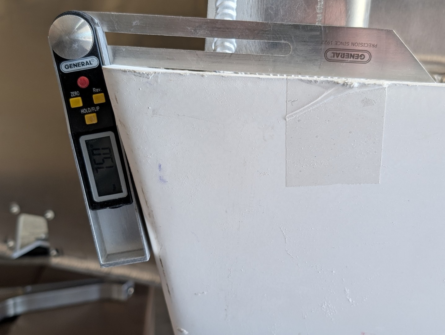
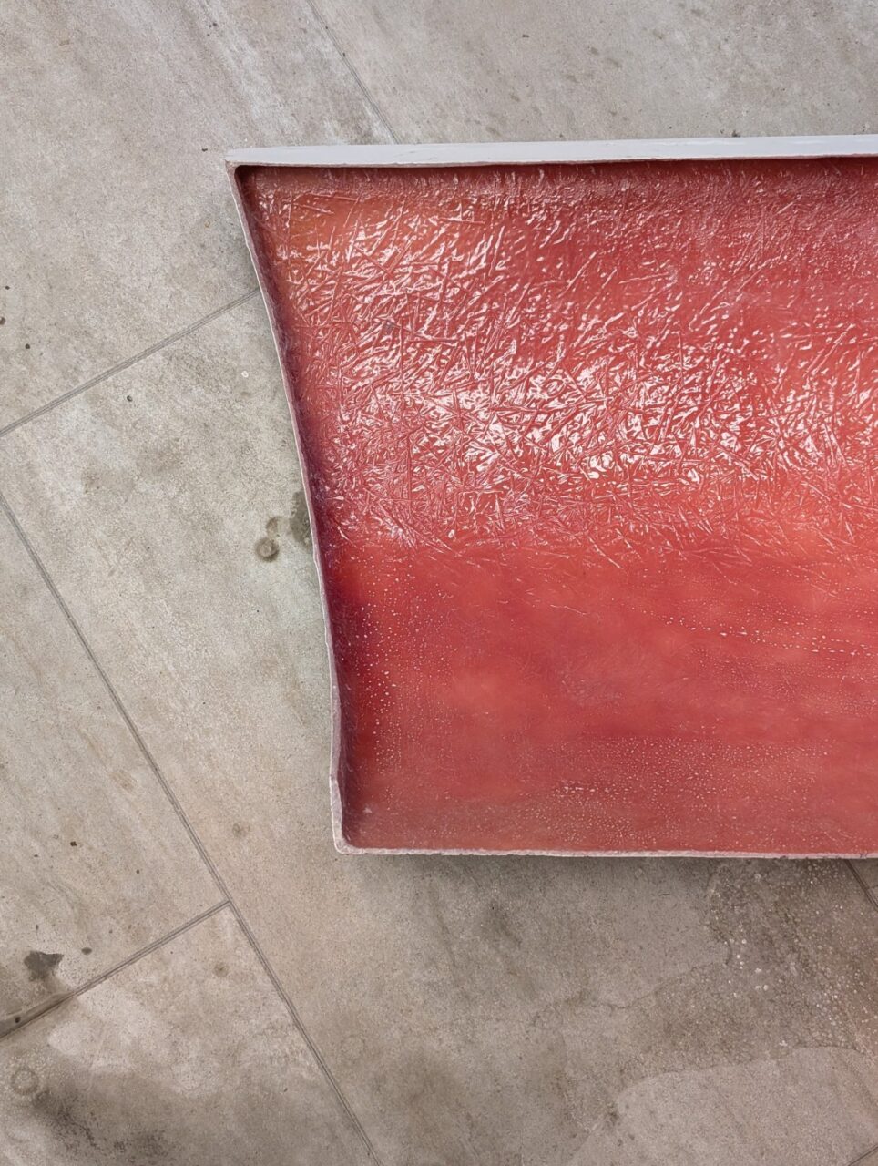
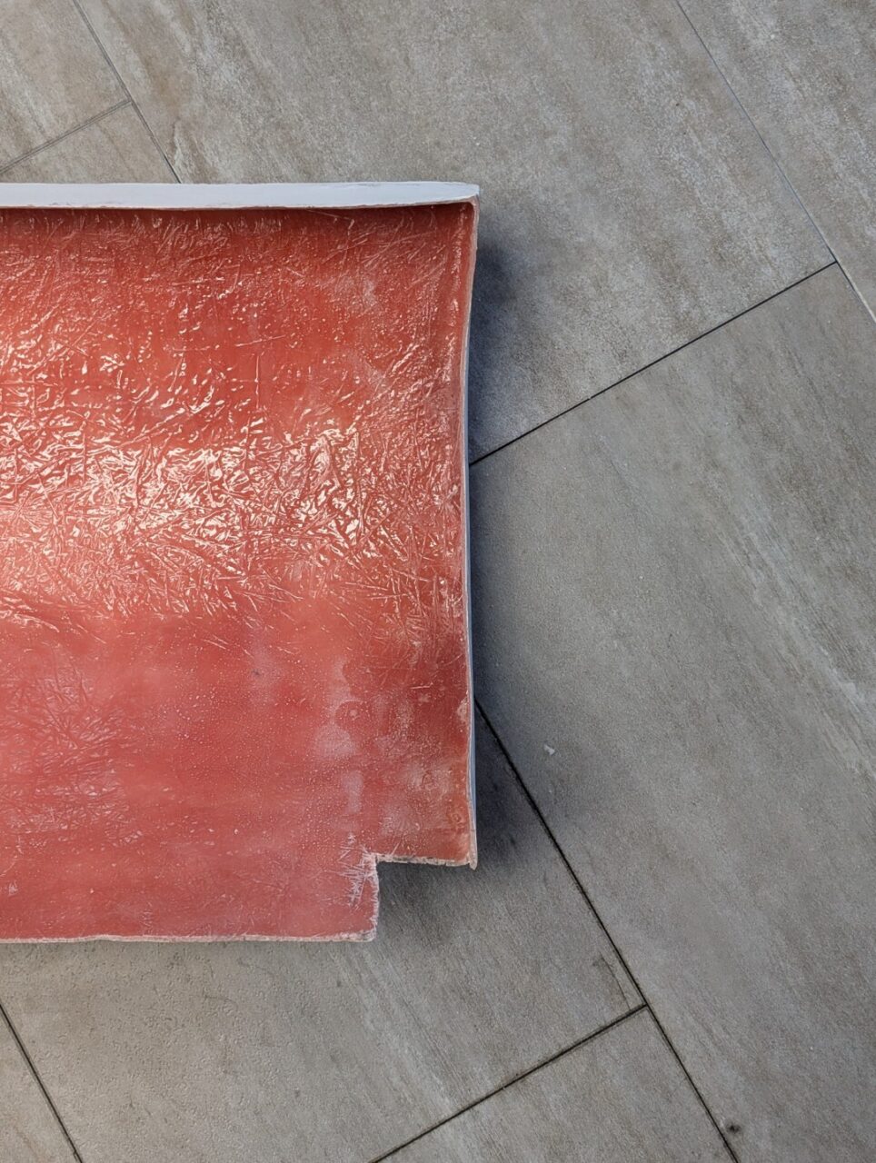
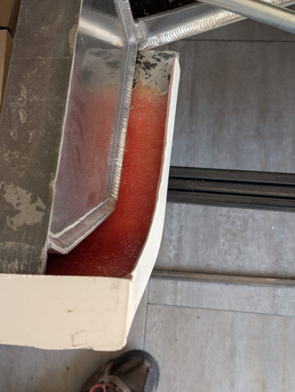
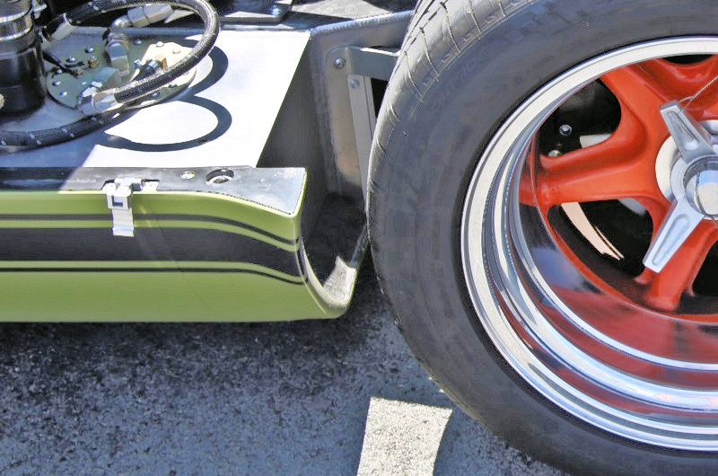
On a trip to RCR, I took some pictures of cars in process and I came to realize we were talking different terms with straight part, curved part. I determined the front of the rocker is the end with the angled cut. The opening angles back about 15 degrees on the front and angles forward about 5 degrees on the rear. Maybe these shots will help clarify this.
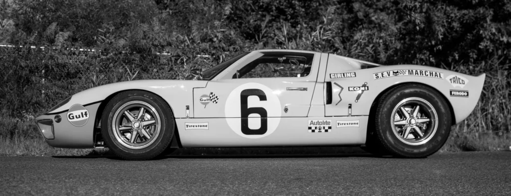
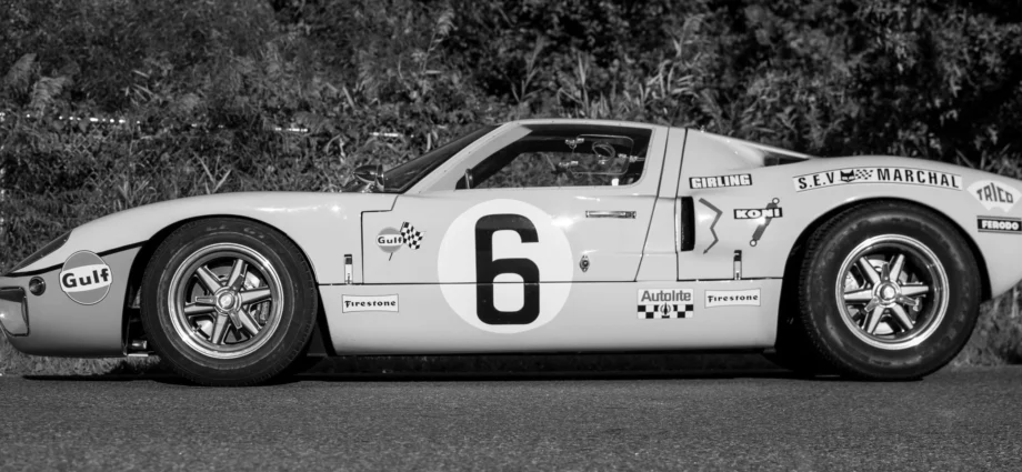
As I was writing this article, I found the header image on the RCR site. It clearly shows the difference in the rocker panel end angles. Had I noted this earlier, it sure would have saved a lot of headaches.
Rocker, front edge
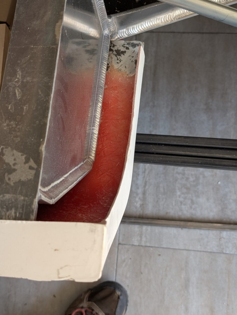
To have maximum clearance for the tire, the rocker must be set as far to the rear as what the chassis will allow. The second picture is looking at the inside of the rocker at the front. It’s difficult to read the digital protractor but the forward edge of the rocker is molded at approximately 15°.
Rocker, rear edge
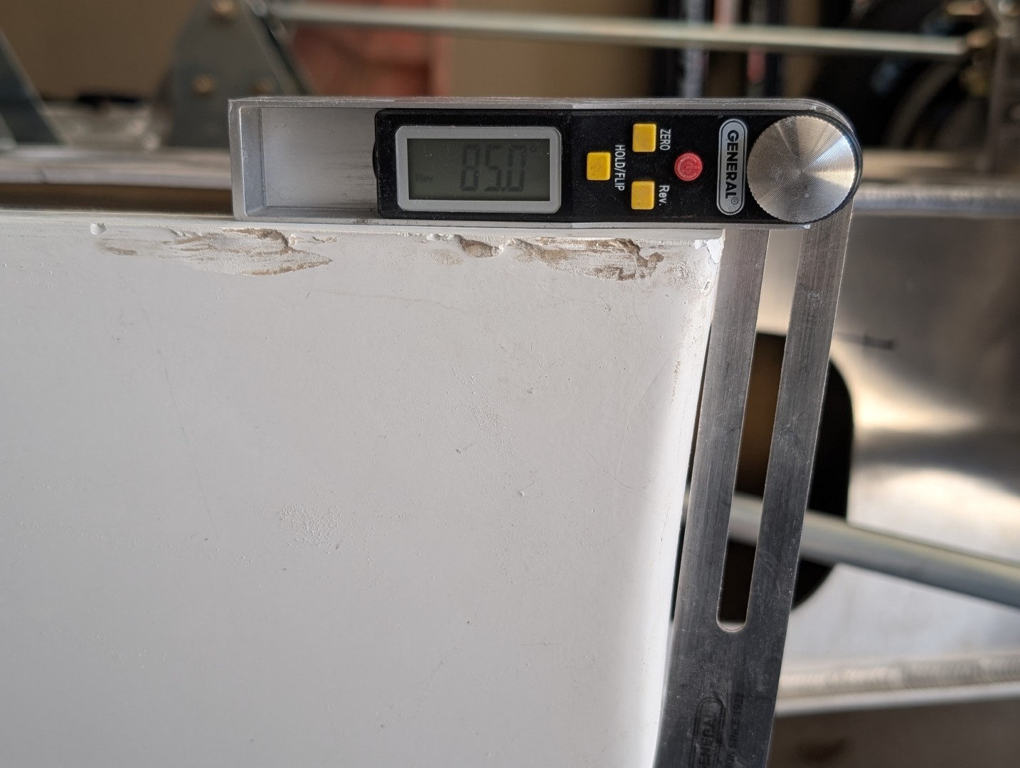
The rear of the rocker, there is an angle to the rear edge, approx. 8.5°. If you are adding flares to your build, this edge will get cut off and replaced with a new flare piece. The second picture is looking at the inside of the rocker, at the rear.

Go back and look at the picture at the top of this page, you’ll clearly see the differenceence in the ends and which goes where.
Mounting and fitting
 Front edge position
 Front edge position
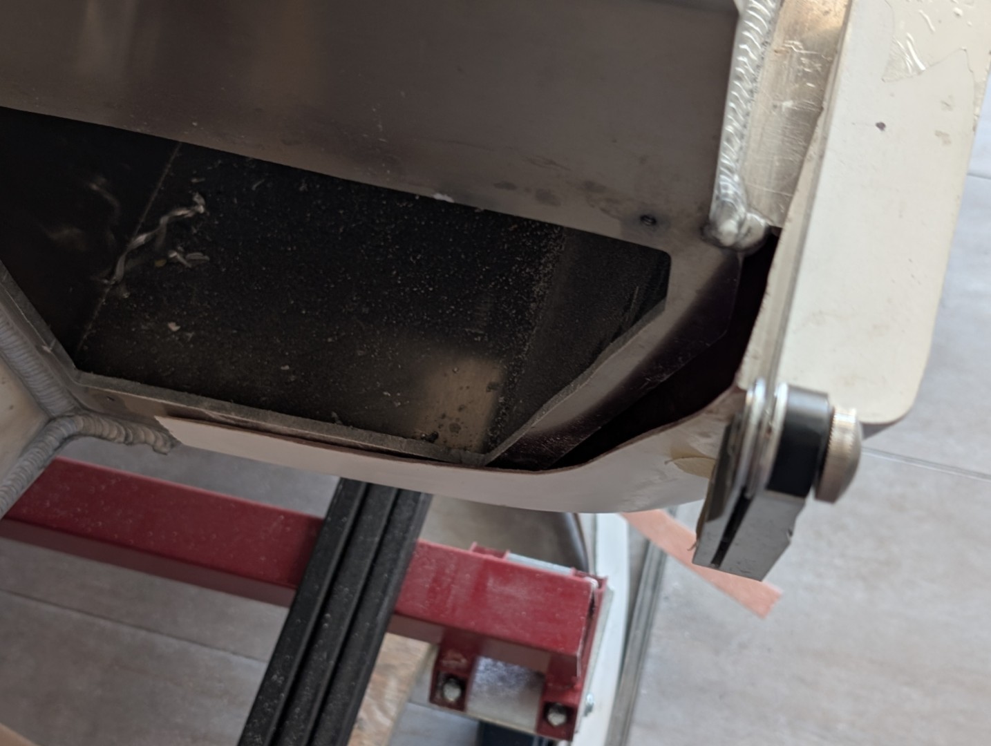
As you work on the position of the rocker, manufacturing tolerances will determine how much the front lower flange needs trimming. Mine required quite a lot to get the edges to match at the upper joint. I ended up with the front edge of the rocker wheel opening 1-1/2″ forward of the aluminum panel welded to the end of the sponson. This will require a fair amount of fiberglass work to finish the inner section and seal the wall edges so rocks and water won’t enter the rocker.
Once the fore-aft position is determined, next comes the width and lip thickness.
The upper lip that sits on the top of the chassis will be visible when your car is completed. If it isn’t already, it should be flat and uniform thickness from the front to the rear. If needed, scuff up the inside and add filler (Kitty Hair) and clamp flat till it cures.
I marked the aluminum chassis with a Sharpie marker to give me a line to set to. I adjusted my rockers till they were parallel to the chassis and 66-1/2″ outside to outside. Make sure they are balanced, left/right. With them in place, I marked and drilled locating holes for the positioning pins.
Position pins
You will have received 8 pins and sockets, used to position the front and rear clips and hold the joints in alignment when the clips are closed. I chose to mount the pins on top the fiberglass rocker panel and the socket in the clips. There is a trick to mounting the sockets which is detailed in the front and rear clip modifications.
I chose to mount 1 pin on the upper cowl surface and built a box for the socket and the other front pin on the rocker panel. It needs to be positioned carefully so to clear the Hartwell clamp base and still bolt into the aluminum chassis. It gets tight. The socket and the latch socket must be taken into consideration, also. When the position is determined, I drilled an 1/8″ hole to mark the chassis.
Same on the rear, except here I used two pins, one forward, one rear, located to miss the socket and latch, clear the body seals and rear edge yet still be able to bolt to the chassis. I’ve seen builds that the pins bolted to the fiberglass and missed the chassis entirely however I didn’t care for that approach. I prefer it be solid. When locating the pins, make sure they are back far enough from the edge that you can get a fastener into the aluminum chassis.
With the locations marked, I then drilled the fiberglass 9/32″ to clear the mounting screw. I drilled and installed 1/4-20 expansion nuts in the edge of the chassis. You will not be able to access the backside of the fastener with a wrench when installing the rocker.
Lower rocker edge
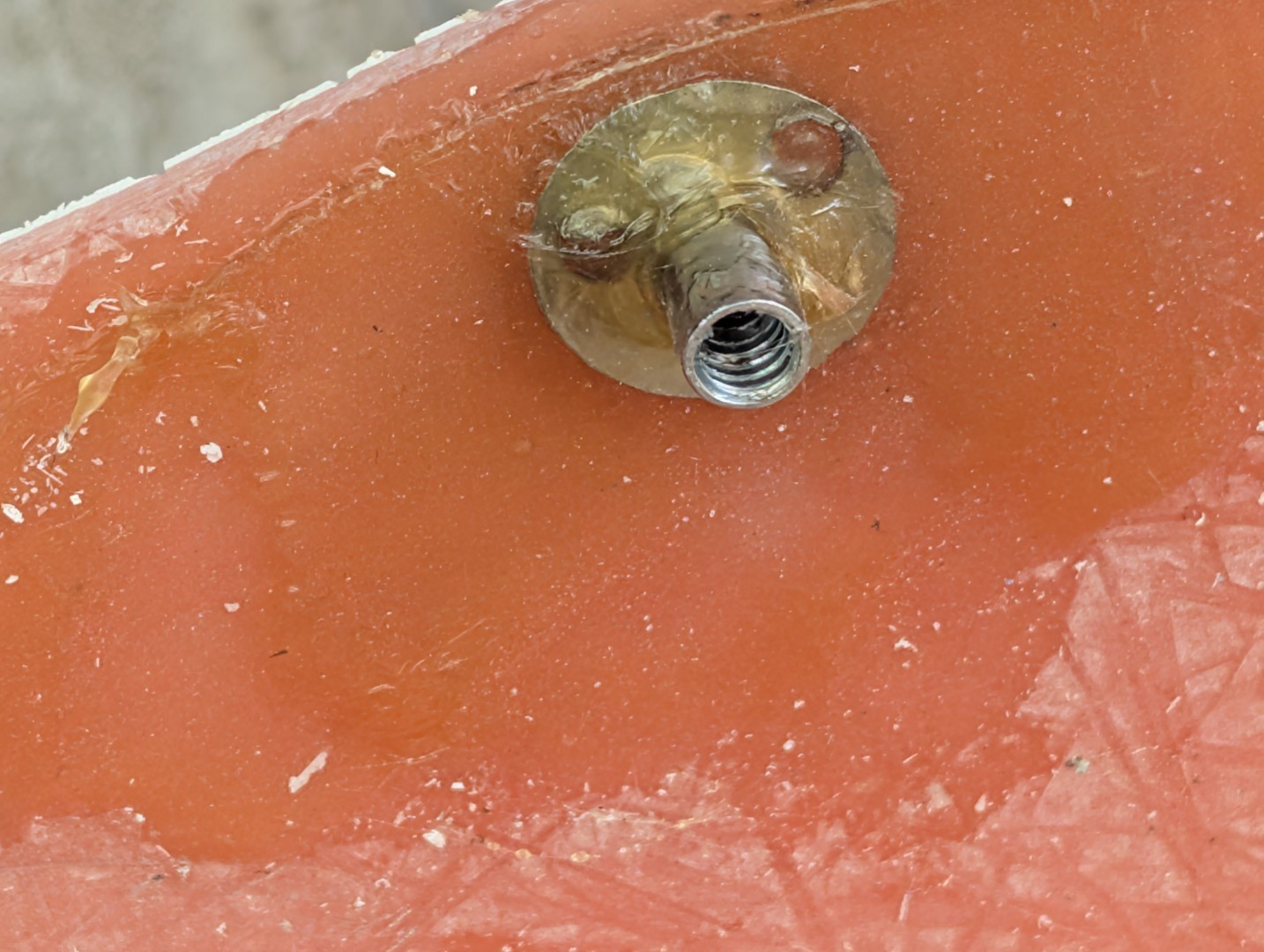
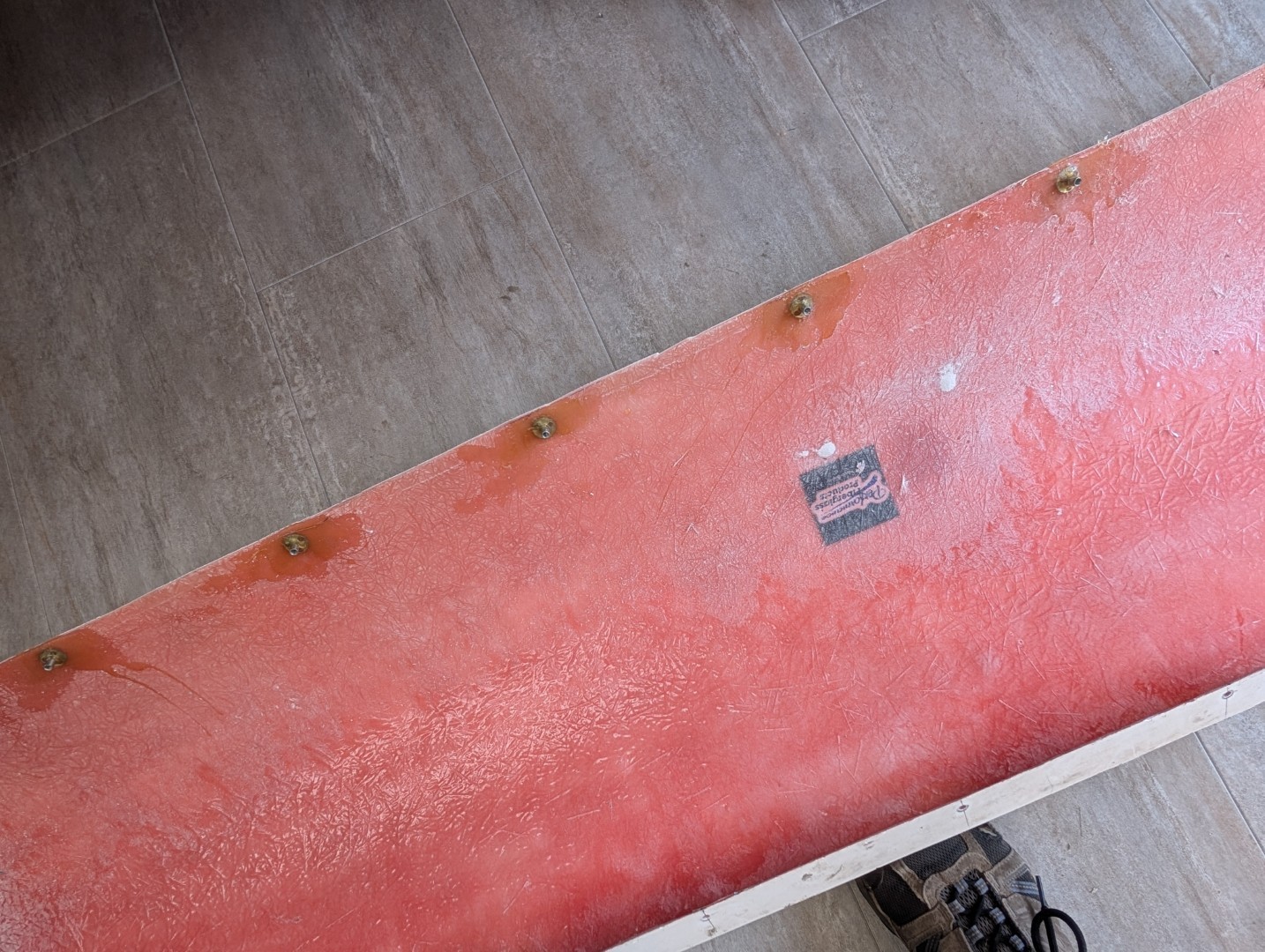
You will note a ‘channel’ on the lower edge of the chassis. The rocker panel sits atop (inside) this channel. You will need to determine where the mounting holes will be drilled in the aluminum, mark the panel, drill and afix some form of anchor nut on the inside of the fiberglass rocker. I used 10-24 Tee nuts, cutting off the little barbs and drilling three holes in the flange. I then glued them in position using MMA310 adhesive.
Rear Edge
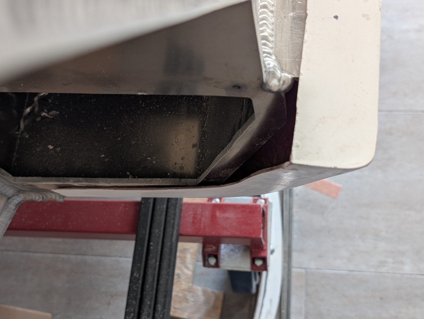
The rear gets a little complicated. The rocker extends about 2-3″ beyond the chassis. The inner edge is unfinished and the opening for the lower radius rod comes into play. A lot of research on the web shows the originals were just left this way. Doesn’t look very finished. The first shot in the gallery is of PXXXX as a reference. I extended the bottom over to the bottom of the chassis and the rear wall to the edge of the opening.
Sealing this area is a real challenge. I added an internal wall that would carry a piece of bulb seal to seal the edge of the sponson and the rocker panel. That would keep water out of the area. I plan to use some closed cell foam to fill the gap at the bottom so any rocks or debris get shedded. The last picture in the gallery shows how Kim Haun did it on his build.