This Section is still under development – Please stay tuned as updates are issued
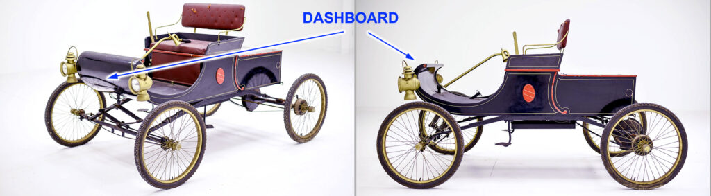
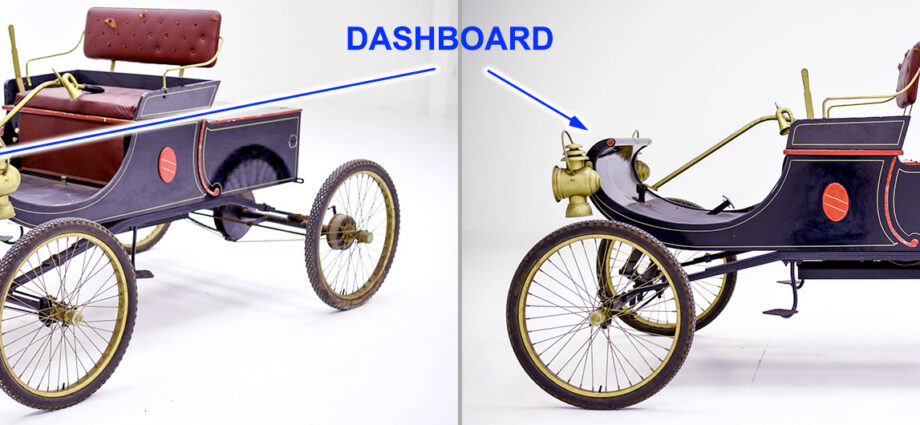
The word “dashboard” originated from horse-drawn carriages, referring to a wooden or leather board at the front designed to “dash” or block mud and debris kicked up by the horses’ hooves. As vehicles evolved, so did the dashboard. The GT40 dash continues this.
When I first made my options list, I decided I wanted to go with the original Smiths gauges. Not a big deal until I received the dash and learned that the Speedometer and Tachometer used by RCR (and the dash) were a different size. Going from a 3-3/8″ to 4″ gauge diameter created MAJOR issues. Then, as I cut the holes for the smaller gauges, I learned the dash fairings for each were not sized to a typical 52mm gauge. Then came the switch plates. What could have been a simple bolt-together turned into a major project.
Oh, and this doesn’t include issues with the A-Pillar interface, demister grill and the removable dash dilemma. I’ve posted details on each.
Removable Dash?
Having owned and worked on Cobras, I know how difficult it was to work on the gauges, wiring or HVAC system. I didn’t want to go there with the GT40. I started with “what do I have to do to make it removable?” There are details on flanging the dash so it clears the base of the A-Pillar and could be unbolted and lifted out. But the angle of the windshield combined with the HVAC plenum, makes this very difficult. The dash would have to be raised almost an inch to clear the plenum; it will not slide back without lifting. And the proximity of the windshield makes this very difficult if not impossible. After a lot of discussion with other builders and owners, I finally realized that if the switch plate area was done properly there really isn’t a reason to remove the dash. It was pointed out to me that if it was necessary to remove the dash, you were into major rework items and you’d probably have the spider removed also. With the spider off, dash removal is simple. With that, I concentrated on making the necessary items serviceable with the dash installed. That really simplified the joint around the A-Pillar.
The basic dash . . .
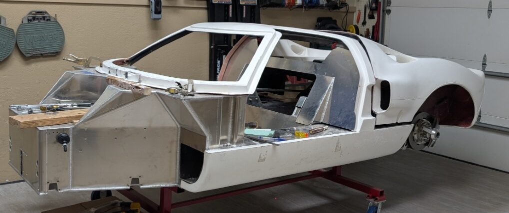
The first process in setting up the dash is to fit it to the chassis. I suspect that when the dash was molded, it was pulled from the mold green and allowed to cure – freestyle. My dash was severely warped, the vertical pieces were on an incorrect angle and too long, the upper surfaces of the dash were not molded concave, I had a chunk of fiberglass that presented itself as a dash. Where to begin?
I determined that the dash is constrained by the underside of the spider and the bottom of the demister area. I began cutting the A-Pillar notches a little at a time till they matched and the feet were trimmed to the level of the sponsons. It took a lot of cutting and fitting. I read Chuck Schmidt’s comment about adding reinforcement to the vertical face of the dash so I glued in 1/8″ spruce plywood.
After several attempts, I finally decided the removable dash was not worth the effort. I concentrated rather on making the seams to the A-Pillar as acceptable as possible.
In the process of fitting the dash, I learned the lower flange was severely warped and would create issues with anything going into or under the dash. I added a 1/2″ tall rib along the rear edge to add rigidity to the part. Your build may not require this but it is something to be aware of.

Speedo - Tach
The larger Smiths gauges will fit the RCR dash, it just takes a fair amount of grinding, sanding and remolding to fit in. I 3D printed some blanks to help form the openings. At the same time, I remodeled the steering column opening to accomodate the adjustable column I had installed. Details on the Steering Column
Smaller Gauges
The RCR (Speedhut 2-1/16″) gauges and the Smiths 52mm gauges are the same basic size. There are two different angled surfaces on the face of the dash for these gauges. Both are flared to put the gauge on an angle towards the driver. But when you bore the 2.062″ diameter hole for the gauge, you learn the flaring was done for a smaller diameter gauge. You end up with the face of the gauge hanging over the edge of the flare. Not a good fit nor was it an acceptable finish.
I chose to mold some 3D printed gauge blanks to serve as a mold for new flaring. This became very tedious as the are in which you are working is very small and constrained. Most work is done with a Rotary Tool and small pieces of sandpaper, Be prepared for a number of tedious days to make this turn out to your expectations.
Switch Plates
With a semi-permanent dash, you have plenty of room to work on the gauges. If you make removeable switch plates, they can be wired to be removeable and wiring becomes a little easier to work on. I suggest mounting the gauges to a piece of plywood to hold them in position so you can make the necessary connections. Your gauge wiring harness should allow each gauge to be removed individually. I recommend either a master plug for the gauge harness, to allow it to be removed for service, or a lengthy loop of wires wrapped and tied to allow you to move the harness out from the dash for service.
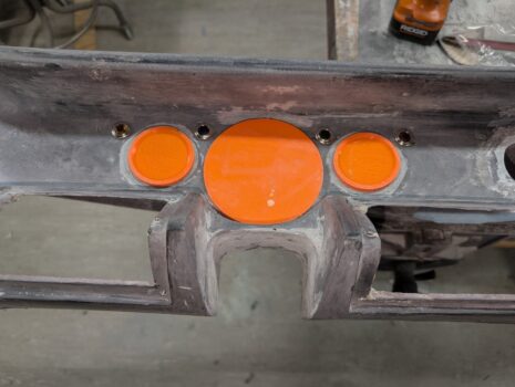
Gauge / Switch Layout
Each GT40 carried a different switch layout as they varied or modified the design of the vehicle. No worry about what is period correct since every one was different. Modern conveniences add additional requirements. This is the layout of my system