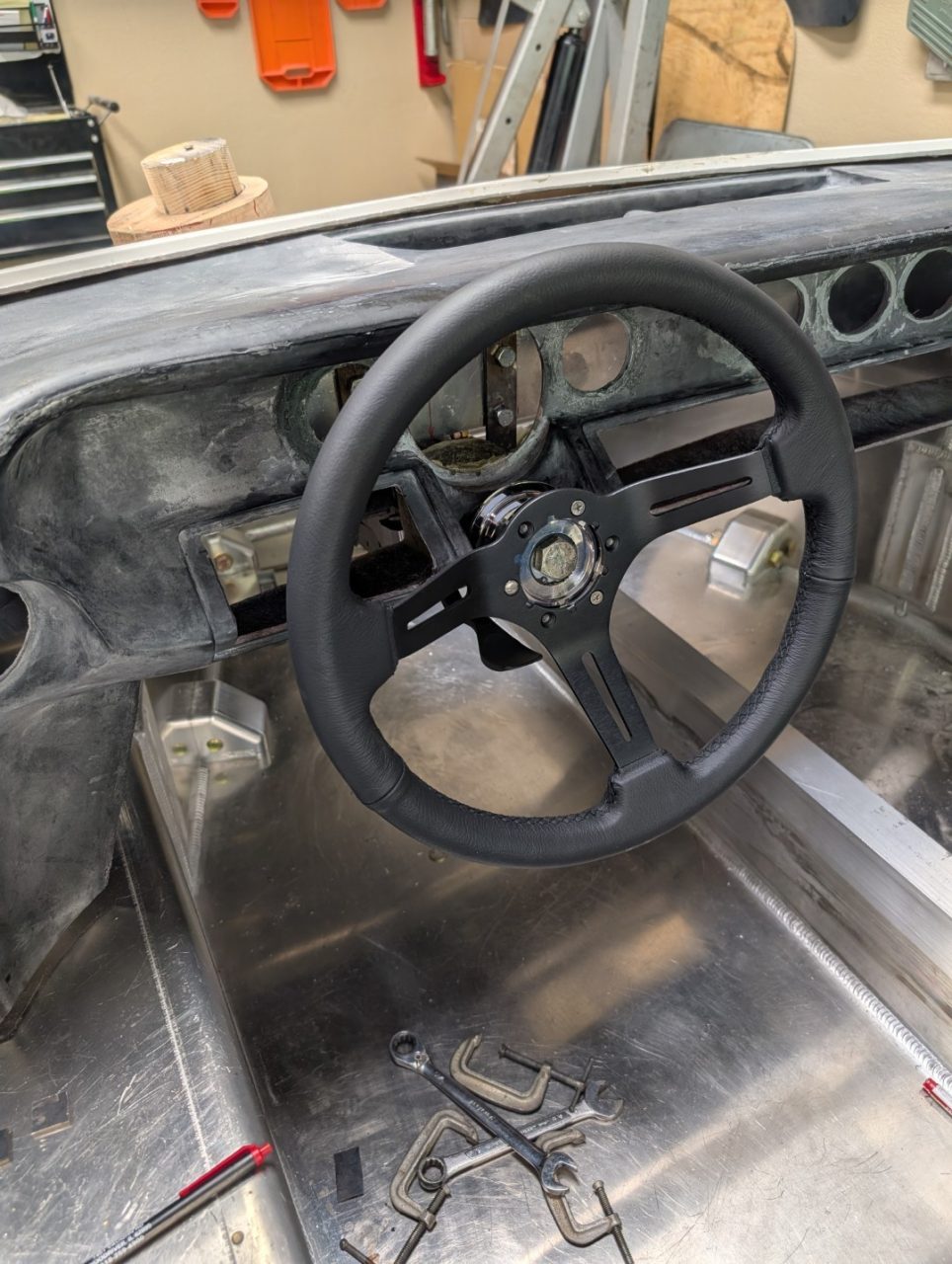
The seats of a GT40 do not move. They are fixed to the bottom of the chassis and rear bulkhead. OK, so how do you accommodate drivers with different heights and leg lengths? In another section, I outline the adjustable steering column – so do the same with the pedals – move them back and forth to fit the driver.
I believe when the kit was first developed, pedal position was fixed to the driver and any changes required unbolting and relocating the pedals. Over the years, a number of different solutions have evolved in moving the pedals. RCR even offers a slider kit as an option. But they all have one issue: the height of the pedals and clearing the steering shaft.
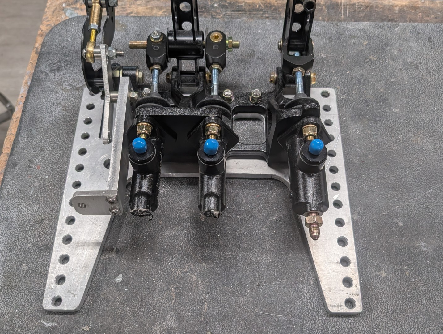
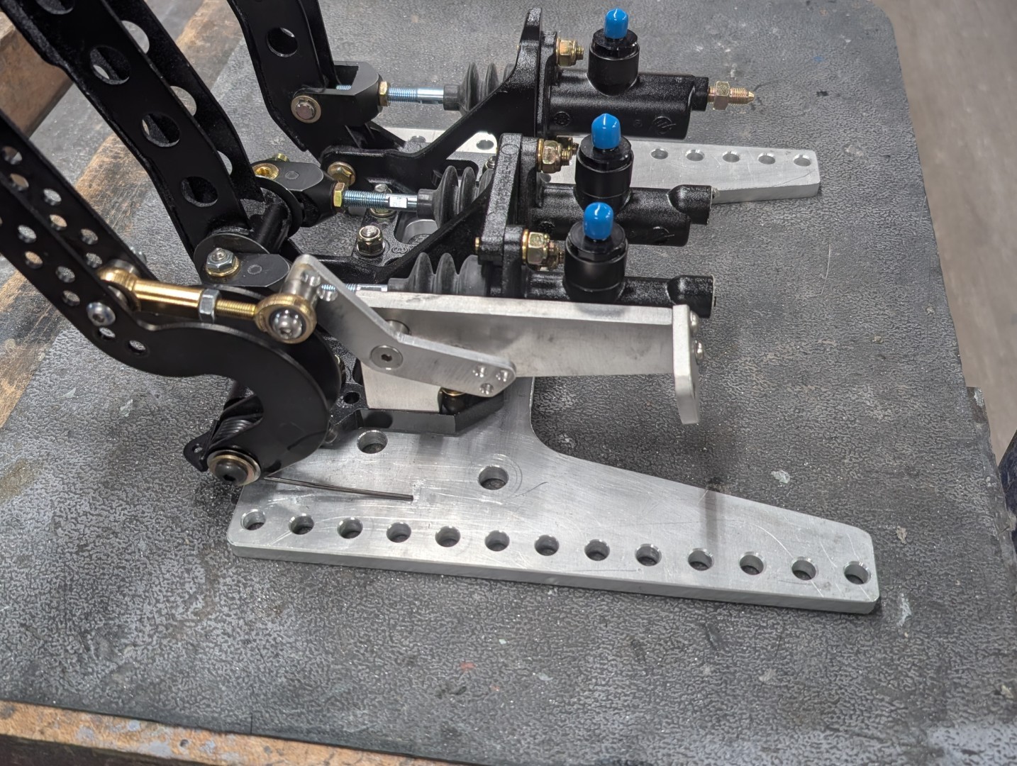
I opted for a middle-of-the-road solution. The base incorporates multiple mounting holes and the bolts are fixed to the chassis. The pedals are adjustable, just not a lift-and-lever-and-move, but a more deliberate “accommodate the next driver.” In my experience, it is rare that these vehicles have different drivers in the same day/week/month. But you need to accommodate one if necessary.
You’ll note my pedal base has multiple mounting holes. These accommodate four plow bolts in the chassis floor. To move, undo four nuts, relocate and re-tighten
Brake lines
The fluid lines for the braking system are accommodated using flexible braided PTFE lines. The inlet side is connected to the fluid reservoirs using a 4AN hose. Output is connected to the braking system using 3AN lines.
Throttle linkage
Throttle linkage is done via a cable that runs along the outer sponson and loops in the front back to the throttle pedal. The size of the loop changes as the pedal system moves fore and aft. The linkage system of heim joints and cable ends reverses the motion of the pedal to match that of the fuel system. The long arm allows adjustment of the linkage and positions the cable system out of the way of the other connections.
Brake Bias linkage
Lorem ipsum dolor sit amet, consectetur adipiscing elit. Ut elit tellus, luctus nec ullamcorper mattis, pulvinar dapibus leo.
Mounting
The system is secured by four plow bolts. Plow bolts are similar to a carriage bolt; however, the head is essentially flat. I wanted as low a profile on the underside. I have located the four bolts then used a die grinder and file to generate the square holes they mount through. On the inside, I used push nuts on the bolt to hold it in place when loosened. The square shoulder holds the bolt for tightening. A slight channel cut at the bottom provides clearance for these push nuts so they don’t interfere with tightening.