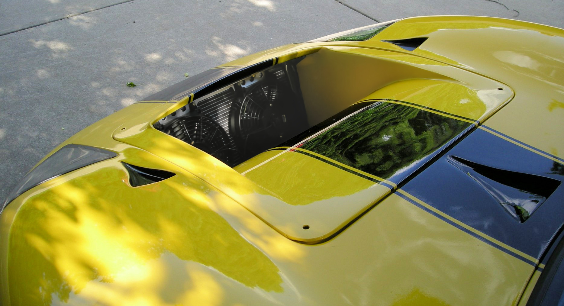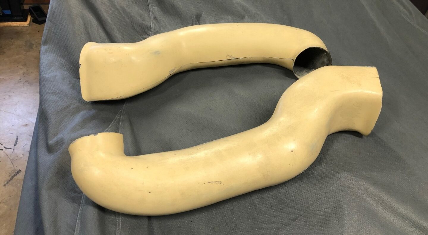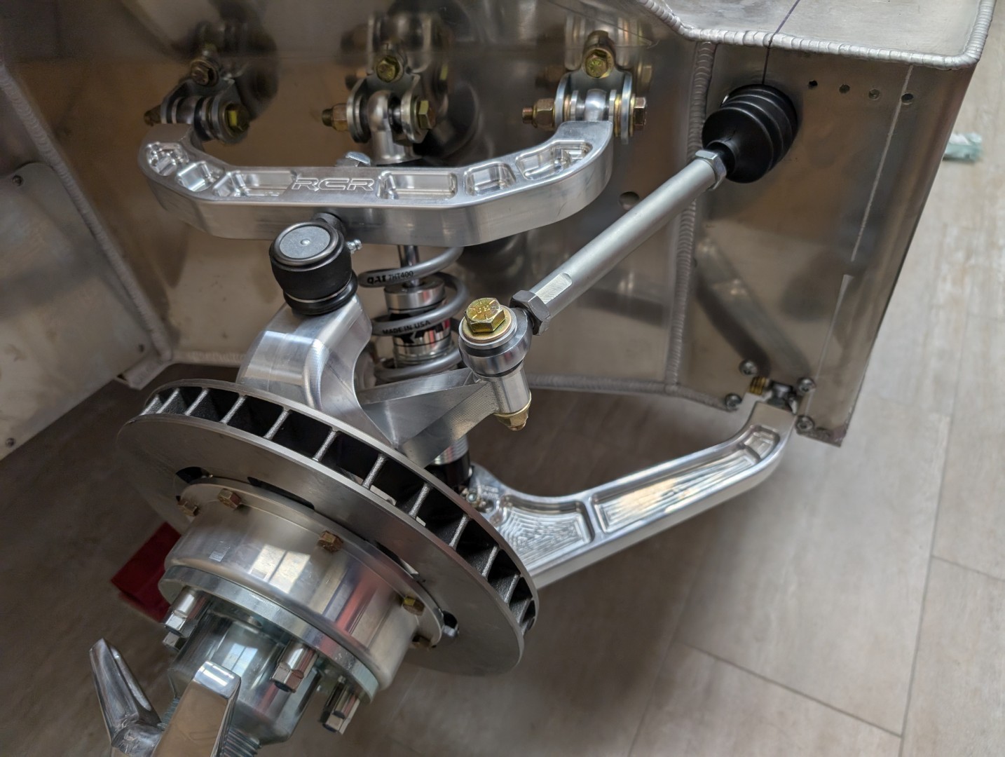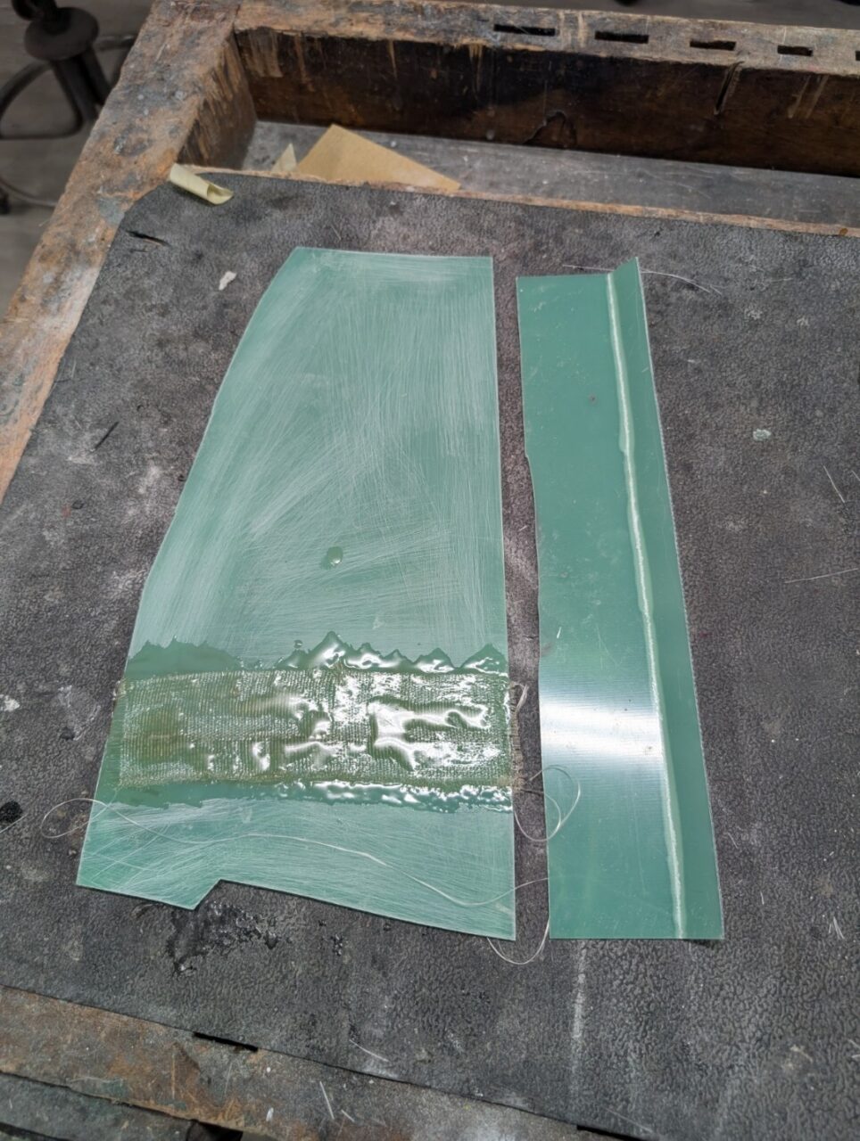
The front clip requires some pretty extensive bodywork, some due to factory errors, some due to my modifications. Comments and details are listed under each section along with appropriate pictures. Some details will have their own data pages and there is a link to those pages included here.
Lower nose/chin
The lower edge of the front clip was one of the worst cases of trimming a fiberglass body I had ever seen. If there was a flange for strength, it had been cut off and the edge was not only crooked, it also varied in thickness. I would build it up to match the front frame and add rigidity to the nose. I saw a post in Tom Shaw’s (Eglitom) build thread how he had added foam to this section so it could be boxed in, adding strength and finishing the nose when viewed. I’ve incorporated that into my build.
Front hinge system
The original GT40s had a ‘lift-off’ nose that rested on bobbins near the front wheels and fastened to the cowl with Dzus fasteners and Hartwell latches. Fine for racing but not user-friendly for maintenance or vehicle displays. Shaw again inspired me with his front frame structure and I followed suit. I used the aluminum nose pieces as the model for my 3D design work. This would give me a structure that would work with the RCR chassis and the fiberglass front clip. This was the first step in my project as I knew the pivoting nose would impact many other parts of the build. Details of the front frame assembly can be found here: Front Frame
Front brake duct & opening
I am undecided on what I will do with the front brake ducts. I doubt they will be needed for most driving.Details on the inner ducting will be forth-coming.
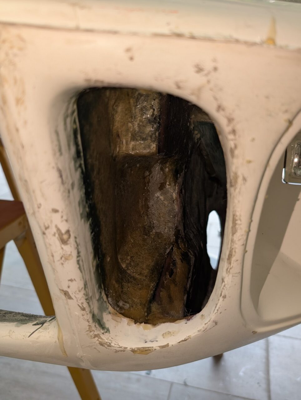
I do know the front brake duct openings require some modeling to make them appear properly. As molded, the nose openings are crude, at best. The side and nose openings are do not direct air well into the radiator. I began the work by separating the two openings and building the front half. I used foam hot-glued in place to form the model around the frame structure and struts. It was tapered and rounded as necessary to clear everything as the clip is open and closed
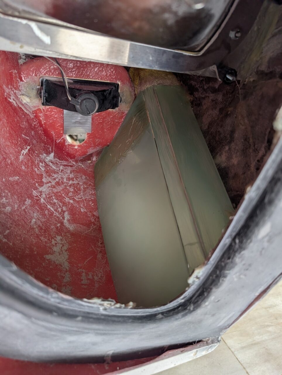
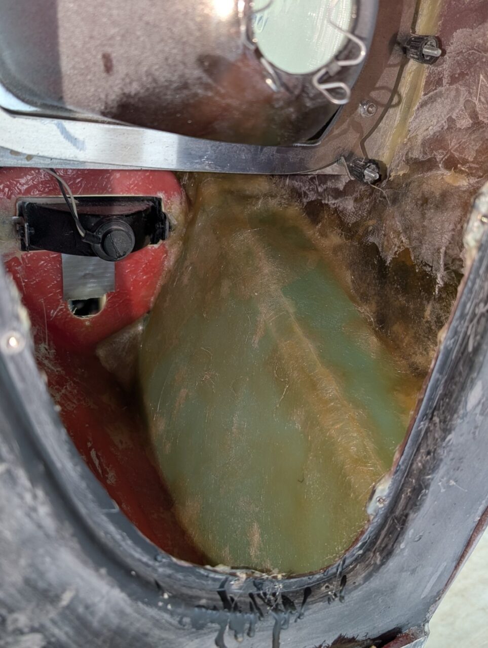
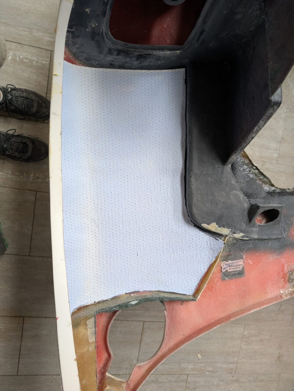
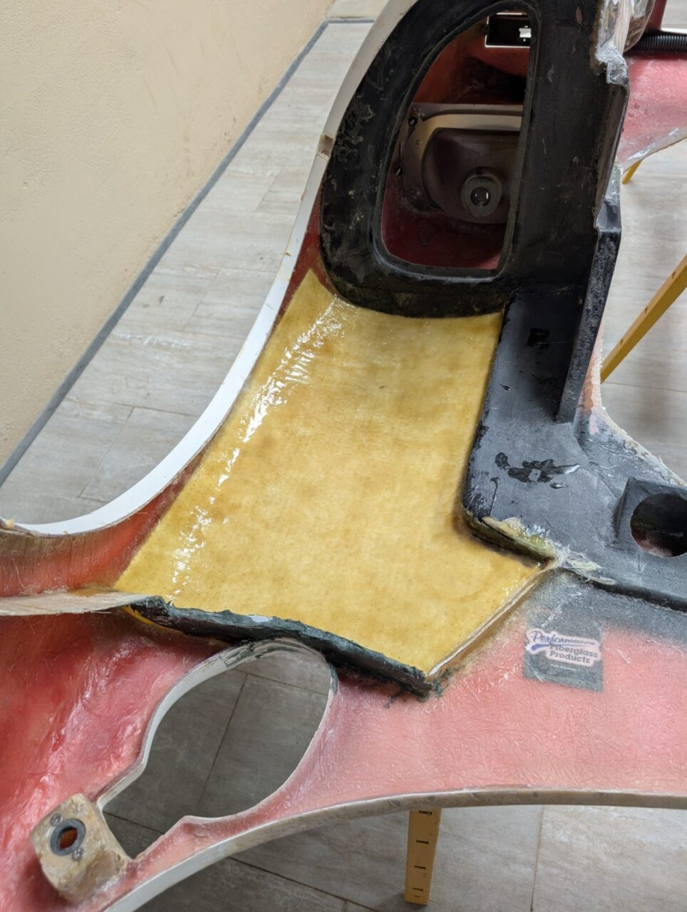
The inner sections are modeled to a 4″ diameter duct at the rear of the inner fender. This needs to be closed off, or the entire light area will get filled with rain, bugs, leaves, whatever. I made cardboard patterns to fit the various forms, then used them as patterns to cut 1.5mm G20 fiberglass sheets. These were then glued in with MMA adhesive then molded over with polyester and fiberglass.
Nostril opening
The laborer who trimmed the nose openings didn’t learn anything on them so his crude work continued with the nostril opening. I planned to use bulb seal around the opening so I trimmed and remolded the edge to accept 3/8″ side bulb seal (McMaster #1120A313)
Front struts
The front struts serve a dual purpose: 1) it’s easier to lift the front clip with the extra ‘oomph’ they provide, and 2) they serve as the stop when the clip pivots to its upward position. As I installed the hinging system, I learned the passenger side inner panel was glued in at the wrong location. It had to be cut loose and moved outward about 1/2″ to match the driver’s side and give enough clearance for the mechanism. I used sgruts from Amazon (#XXXXX)
Locating pins & sockets
The front panel really isn’t wide enough for two alignment pins so I decided to put one at the lower rocker panel and the upper on top the cowl to align the top of the clip.
Lower Pin
The position for the pin gets tight. I wanted it mounted to the aluminum chassis but it needs to be far enough forward to clear the Hartwell latch base. Remember the rule “Measure twice, cut once” Fiberglass can be easily repaired but if you drill the aluminum in the wrong spot, you’re going to need a TIG welder to fix it.
The main purpose of this pin is to align the bottom edge with the rocker panel. You can adjust it in and out to get it right then mark and drill. I used 1/4″ RivNuts in the aluminum chassis to accept the locating pin screw.
Upper Pin
Mounting the pin is pretty easy; there’s all kinds of aluminum to drill on the upper cowl. But the box that carries the molded socket is a different story. It needs to be at the back of the gas cap opening, but inside the clip and over the aluminum cowl so the pin can be mounted. The pictures should be self-explanatory
NACA ducts
The NACA ducts are the small recessed ducts on the front of the car and the one centered under the windshield. Their design allows for airflow like from a scoop however there is minimal or nor drag associated with it. I think it important that all features of the car be functional so considerable time was put into constructing the internal ductwork and routing it into the interior HVAC system. This link will take you to the details of that project: NACA ducts
Wheel opening
The wheel openings presented a couple different issues. 1) the clearance between the tire and the openings as the wheel turns in and out is very tight. I had to trim the flanges considerably. 2) the body is not symmetrical and the passenger side had to be remodeled to fit the tire. I used a piece of cardboard to trace the opening and put a hole that slipped over the axle hub to anchor it. I then moved it to the passenger side and marked the body accordingly. The front edge of the opening had to be enlarged considerably.
Rear edge /wiper opening
Lorem ipsum dolor sit amet, consectetur adipiscing elit. Ut elit tellus, luctus nec ullamcorper mattis, pulvinar dapibus leo.
Cowl supports
Lorem ipsum dolor sit amet, consectetur adipiscing elit. Ut elit tellus, luctus nec ullamcorper mattis, pulvinar dapibus leo.
Inner fenders
Front
The MkI clip comes with the forward wheel wells formed in place. They include cutouts to access the headlight and parking lights however the cover is not included in the kit. I cut a panel from .060″ aluminum and drilled it for 6 mounting screws. Using those holes, I drilled the flanges to accept adhesive nuts.
Inside Panels
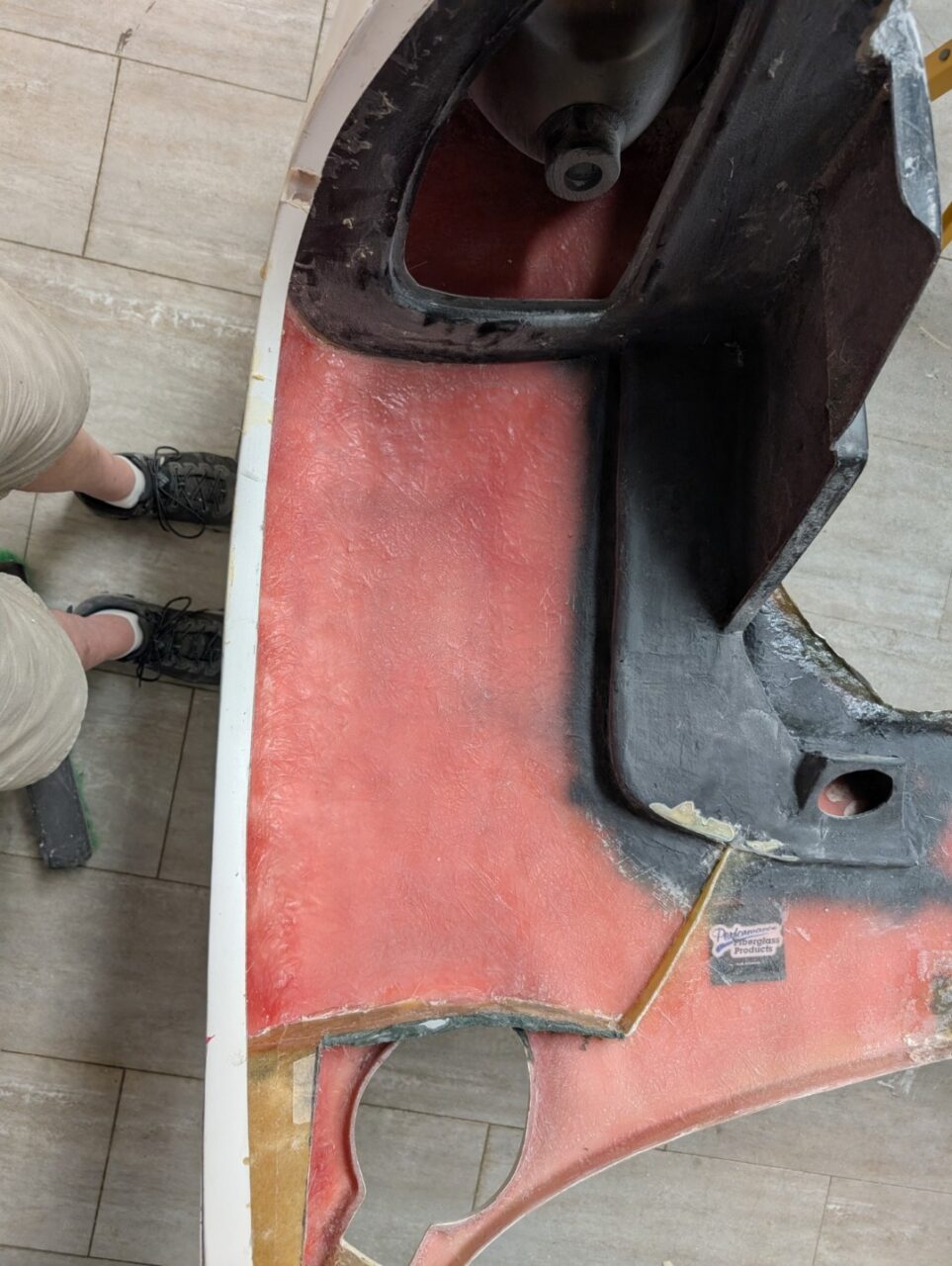
The inner panels are formed however two issues. 1) the panels are designed for the slide-off bobbin system which I did not use. I converted to a pivoting front clip. The inner panels had t be remodeled slightly to make room for the struts to operate. 2) as I worked on this conversion, I learned the passenger side inner fender had been mounted 1/2″ inboard. It became necessary to cut the bonding adhesive and relocate the panel.
The inner panel also consists of an aluminum panel mounted to the front frame. This will be designed and mounted later. More details are in the front frame section
Rear
I wanted the car to be as waterproof as possible. Living in the Midwest, we are fair-weather drivers, but it does happen that you get caught in a shower or thunderstorm. The cowl pieces form a solid wall to keep the water out, however the edges form a perfect path to route tire splash directly into the cabin.
I fabricate fiberglass panels to close off the front clip where it closes around the cowl. These panels are capped with bulb seal that seals on the cowl walls and top when the clip is closed. It also adds considerably to the rigidity of the clip
Inner fender protection
Once the internal structure of the clip was completed, I added a layer of 2mm Coremat to the top inner fender. This will also be coated with bedliner to cut down on the possibility of rocks causing star chips on the painted surface
Wiring conduit
The pivoting front clip poses a challenge for wiring to the headlights and turn signal lights. The wiring harness must flex near the pivot point and it is better if this is done at just one point rather than both sides. I added a conduit recessed under the nose front opening that allows wiring to enter and then run to the right and left sides.
Nostril
I opted to go with the two port nostril. As I began the process of fitting it, I ran into a number of issues.
Front clip opening edge
The raw fiberglass was very uneven and would not be suitable to serve as an upturned edge like many originals displayed. I chose to use a bulb seal on the edge to seal the opening to rain and water. McMaster #1120A313. This required squaring up the edge and trimming around the opening. Not a big deal but more Bondo work. I would mount four spacers near the Dzus fasteners so the height would be consistent
Corner fasteners
I planned to use the winged Dzus fasteners as used on the originals. That would require a little work on my part as they are no longer available. I would have to fabricate the wings and locating the long fasteners became an issue. I finally found them at Primus Racing, a supplier in Florida to the F1 community. Part number PANE51100, they are 5/16″ flat head slotted steel fasteners, 1.10″ long. With my body thicknesses, I was able to use a .250″ spring.
I then drew a pattern for the wing in DXF format. I’ve attached it as part of the gallery below. I was able to order them in Stainless Steel from SendCutSend. I would modify the slot in the screw to accept the wing and then braze them together. Pictures will follow as this is work in progress
Nostril Openings
As I positioned the nostril, I found the openings did not match the radiator or fans, not even close. A little research on the innerwebs and I’ve learned the originals were made this way.
- The nostrils left the bottom open about 5″-6″ Why this was done is lost to history. But many teams modified their cars by adding an aluminum deflector at the bottom of the radiator to get the air started towards the outlet.
- The originals operated without fans. I guess at 150MPH, the fan was not really needed. But for us street drivers, I has to be part of the equation
- Many builders have noted this and also modified the nostril for another reason. Seems with the standard opening, the front clip area becomes very hot from the air that doesn’t get ejected, making the footbox extremely hot. I am led to believe the GTD brand was the first to pioneer what they called a dropped nostril, the lowered the front edge down to the bottom of the radiator, sealing the front clip to warm air and directing it out into the airstream.
I am currently working on which method, the dropped nostril or the aluminum deflector is best. Details to follow